Earlier blog entries on the EMA Blog introduced new features available in PCB editor 16.6 that enable efficient ECAD/MCAD collaboration (IDX) and realistic 3D visualization (STEP).This article will discuss some techniques engineering teams can utilize to ensure quick and accurate 2D/3D model synchronization.
Defining a Common Language
First let’s discuss orientation. Properly linked ECAD and MCAD models models must share a common orientation across the x, y, and, z axis. PCB Editor allows you to orient the 3D model with the 2D footprint on the fly however; this can become a time consuming process especially when 2D and 3D models do not share some common characteristics. To enhance the STEP model association in PCB Editor, a process can be adapted that coordinates synchronization of the 3D STEP model and the PCB Footprint DRA file. This would include X&Y coordinates, lead pins/ package to pcb plane reference (z=0) and part centroid/ pin 1 origins.
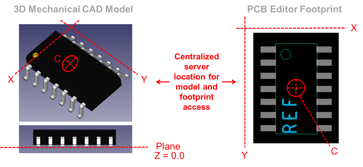
To more effectively coordinate these symbols via a standard, both the MCAD and ECAD librarians should be versed in the usage of the IPC-7351 specification. This spec will serve as a reference for most common part packages and will dictate origin, rotation and naming conventions. Other non-standard IPC packages could be based on an internal standard developed by the ECAD and MCAD teams.
EMA Product Highlight:
EDABuilder provides an automated way to quickly and accurately build PCB footprints to IPC-7351 or any custom specification.
Building to a shared standard will ensure quick and accurate orientation between the ECAD and MCAD part libraries. It will also provide a common language for efficient communication when problems arise and changes need to be made. Now that you have a common framework to create your libraries the next step is to create a centralized, managed repository to store these libraries and keep both design teams in synch regarding any changes.
Centralizing Your Libraries & Managing Notifications
ECAD & MCAD teams should have a common repository/ server folder for housing their 3D Models and PCB Footprint files. This common shared space will ensure designers are always using the latest and properly coordinated models and footprints. If a misalignment occurs, a user or librarian can adjust models and then have it corrected/ changed for any future use.
Depending on the data management tools you have employed in your organization this space can also be used to notify affected parties of changes to these models to ensure everyone remains in synch throughout the design process.
By adapting a process of collaboration utilizing IDX and STEP with your MCAD software and the Allegro/ OrCAD PCB Editors, engineering teams can effectively and accurately manage data interchange between their ECAD and MCAD design environments.
