Make Inductors, Zeners and Sources easily with the new PSpice Modeling Apps
If you have PSpice v16.6 with ISR 006 (Interim Service Release) or higher, you have all that is needed to run the new PSpice Modeling Apps available for free from Cadence on the OrCAD Marketplace.
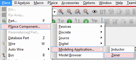
By installing the TCL based PSpice Modeling Apps on your system you will get three new available productivity apps in the Place > PSpice Component… submenu when on a Capture schematic page. These parameter driven apps have been created to assist in the previously complex tasks of making inductors, zener diodes and sources. Let’s take a closer look at them here:
Independent Sources
Available from Place > PSpice Component… > Source > Independent Sources
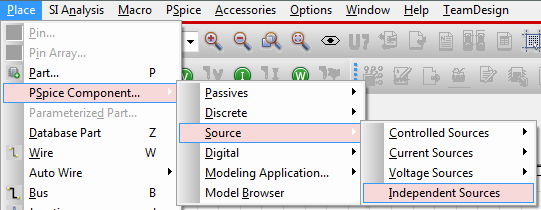
This app has a comprehensive list of different types of sources that you may require in your transient simulation including voltage and current versions of Step, Pulse, Square, Ramp, Sawtooth, Reverse Sawtooth, Triangular, Sine, Cosine, DC, Exponential or FM (Frequency Modulated).
For an example, let’s look at creating a Voltage Sawtooth waveform. On the Pulse tab, choose the Voltage radio button then the Sawtooth radio button and once you have filled in the desired parameters, hit Place; your part is ready for simulation!
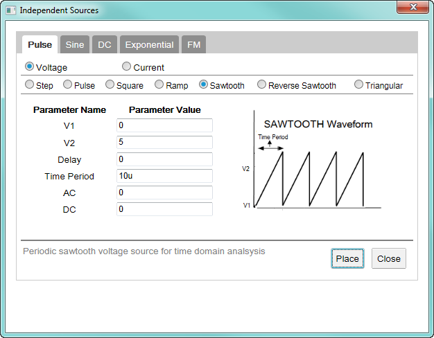
For all these sources, all the entered data is stored on the placed part itself so there are no libraries to add or configure at all. Put it into a simple circuit and take a look at the results:

This is so much easier than fiddling with all the TD, TR, PW and Period properties that you used to have to work with on the VPULSE part!
Inductor
Available from Place > PSpice Component… > Modeling Application… > Inductor
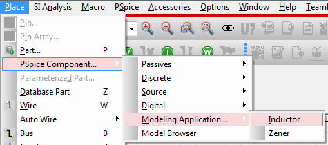
Creating realistic inductor models required a pretty complete understanding of PSpice subcircuits, their connection to a Capture symbol and library management making them relatively complex parts to make, create, manage and edit.
With the Inductor Modeling App this becomes trivial. To make a non-ideal RF Inductor in PSpice, invoke the app and specify 3 or 4 parameters (Inductance, DC Resistance, Self Resonance Frequency and (optionally) the Parallel Resistance) and give the inductor a name.
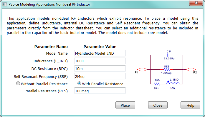
Hit Place and an inductor with the value you specified will be placed in your schematic.
![]()
All the underlying intelligence based on what you just entered is stored in the linked model which has been created in your -PSpiceFiles/PSpiceModelApps directory and configured at the profile level to work in your present design. There is nothing you need to save or configure to make this part work, it has all been done!
If you’re curious, you can verify the contents of the inductor by right clicking on it and choosing Edit PSpice Model to open the PSpice Model Editor and see everything that you entered, now in PSpice formatting.
.SUBCKT MyInductorModel_IND P1 P2
RDC P1 PI 10m
L_IND PI P2 100u
RP P1 P2 100Meg
CP P1 P2 6.33252E-11
.ends MyInductorModel_IND
Zener
Available from Place > PSpice Component… > Modeling Application… > Zener
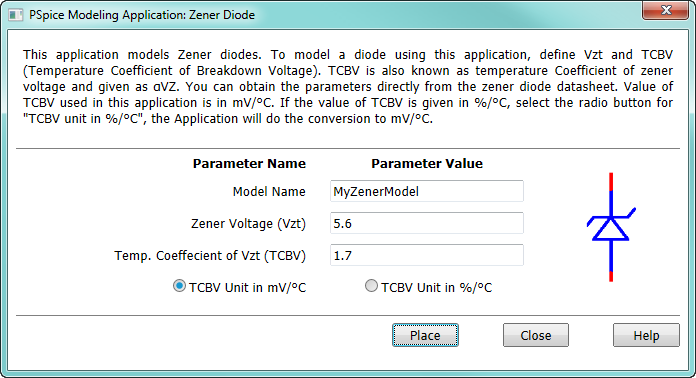
The Zener Diode Modeling App is quite similar to the Inductor Modeling App above. In this app, you’re going to enter the Zener Voltage (Vzt), the Temperature Coefficient of Vzt (TCBV) in either mV or % per degree C and give it a name to get a thusly modeling zener diode ready to use.
The part once placed, reflecting the Vzt value you entered:
As before, nothing needs to be done at this point as far as saving or configuring libraries, you can go right ahead and simulate with it!
If you take a look at the library file (right mouse button > Edit PSpice Model), you can see the parameters that you entered have made their way to the model itself.
.SUBCKT MyZenerModel AN CAT
+ params:
+ VZT=5.6
+ IZT= 20m
+ ZZT= 11
+ TCBV=1.7
+ IR= 1u
+ VR= 1
Like the Inductor Modeling App above, this is a very convenient way to create and quickly use a zener diode with some basic properties in just a few clicks.
Besides the present features that these apps brings to PSpice, it also shows the direction that PSpice is heading with models that can be created and brought into PSpice much more easily without needing to have expert understanding of models and library configuration.
BTW – If you haven’t checked out all the apps available in the Marketplace, there are a lot of others there that you may benefit from (see EMA Store).

