Most of the PCB designers I know are creatures of habit just like I was…
We have our favorite colors, layer names, customized keyboard and our number one goal is to see how many nets we can route in one day. Very rarely do we change – but when we do it’s either because we changed employers or we are forced to because the tried and true processes don’t work any longer.
Can you relate?
Those of you who were fortunate enough to attend past CDN Live conferences may remember that, as a customer I used to present a session called “Allegro Tips – Did you know … ? In all fairness, my presentations were called that because I was an Allegro user, but having joined Cadence roughly two years ago I have come to hear from and appreciate the many loyal OrCAD users out in the community that are creating some bleeding edge designs.
So, back in early 2016, at the last CDN Live Silicon Valley edition, we revived this very informative session – at least that is what some of you told us – but this time with a new name – “Cadence PCB Editor – Tips & Tricks – Did you know … ?” As a secondary piece to this revival, we are also starting a similar blog that hopefully will give all users of Cadence PCB Editors valuable tips and tricks that may make you stop and think about different options open to making your design process faster and easier and hopefully more productive. Change can sometimes be good for you.
Therefore, without further ado, with my opening blog, I offer up to you, our valued readers, Vince’s Favorite Usability Features from V17.2-2016. We hope you find them very informative and helpful. Check back soon for additional PCB-related blogs.
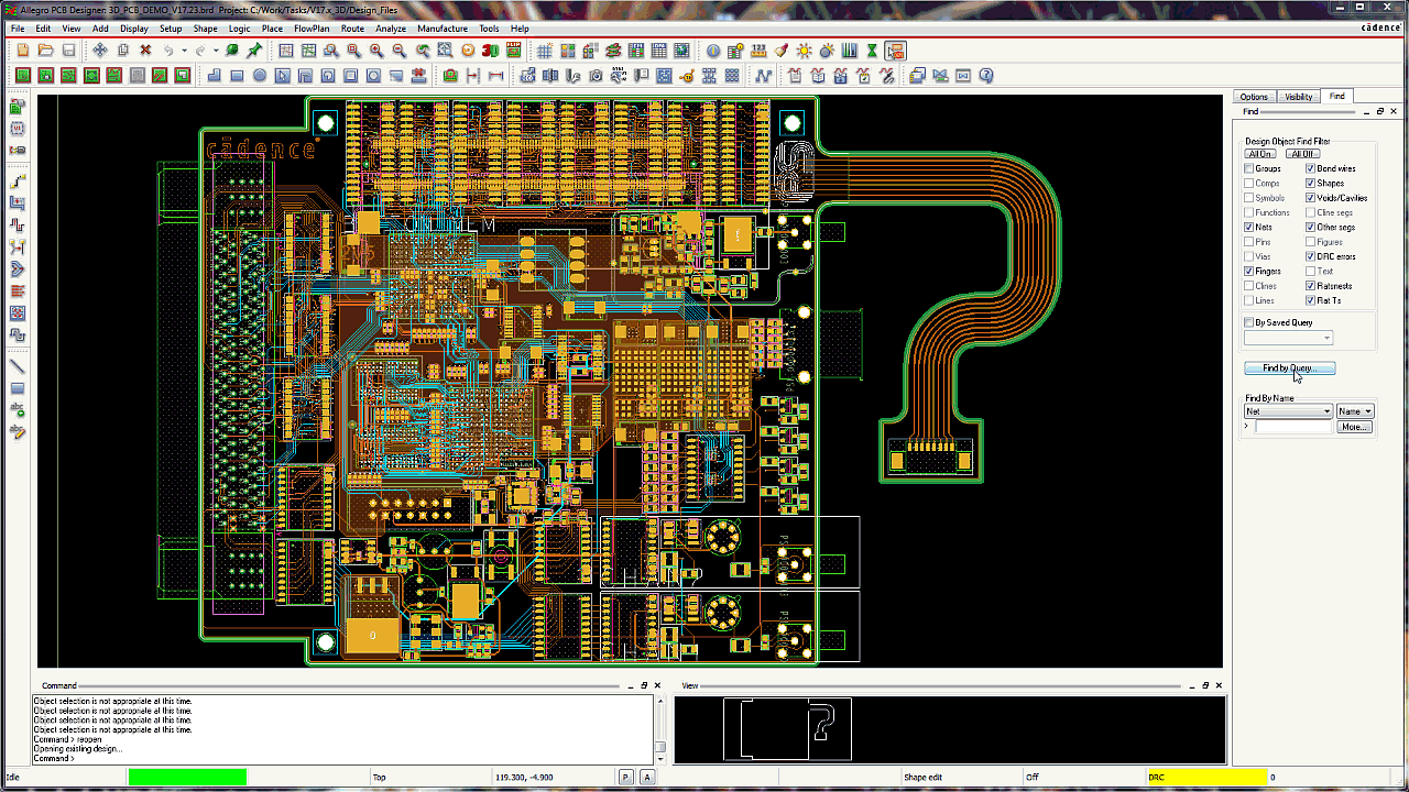
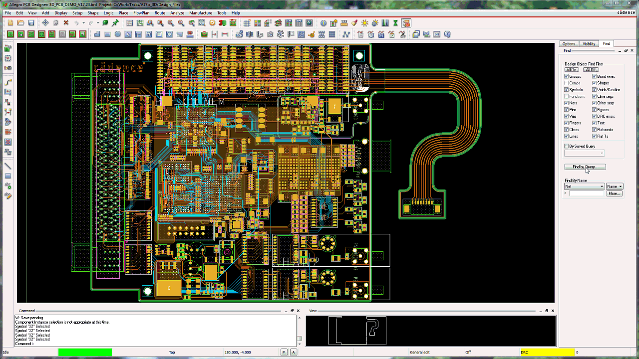
1: FbQ – Find by Query
We introduced a new and powerful relational query engine in the V17.2 QIR1 release. You can use FbQ to easily and quickly locate design objects within any size of design – large or small. With a few simple clicks, users can create, use, save and recall time saving queries.
Have you discovered how powerful this new feature can be?
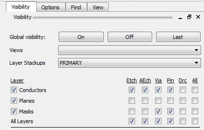
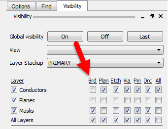
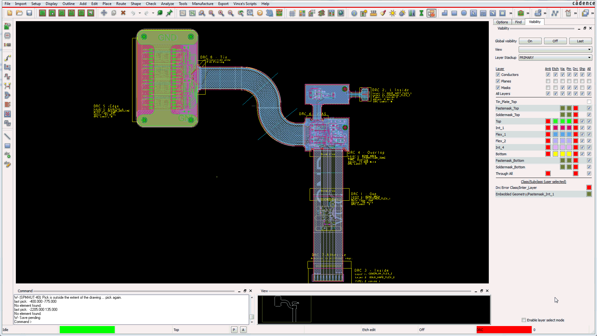
2: Customizable Visibility Pane
We enhanced the Visibility Pane to allow designers more efficient access and control of layer content. Instead of a single stackup approach, the Visibility Pane now gives you quick access to different Zone stackups if you are designing rigid-flex PCBs. This pane now has the added benefit of being able to control layers other than electrical.
Customization of the Visibility Pane is done from the Visibility Pane tab in the Color Dialog.
Using the Visibility Pane Configuration settings, a user can tailor the Visibility Pane to their liking by turning on/off the following information rows:
- Global Visibility
- View Selection
- Layer Stackups Selection*
- Layer Conductors
- Layer Planes
- Layer Masks
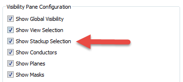
*Note: Stackup Selection with the Layer Stackups dropdown will only be available (for turning on or off) in designs that contain more than one zone in the stackup.
You can also configure which columns to display in the Visibility pane. Simply drag and drop or use UP arrow to add classes to the Visible Classes sections so that they are visible on the Visibility Pane.
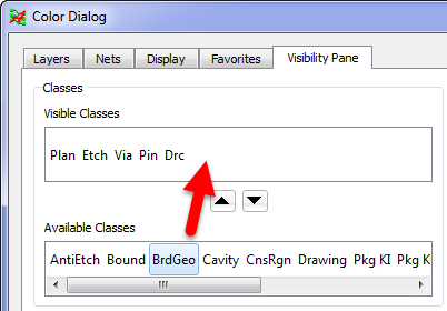
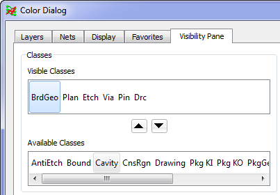
“Board Geometry” added in the above step is now added to the Visibility Pane.
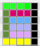
Use the sliders to control the size of the color boxes as well as the spacing between the color boxes on the Visibility Pane.
Slider to control color boxes:
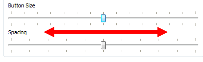
Smallest button size with largest spacing:
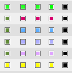
Largest button size with smallest spacing:
Color control made easy. Let us show you how!!!
3: Layer Select Mode
We enhanced the Visibility Pane to allow the user to go into “Layer Select Mode”. This action puts the canvas into a “single layer” view and allows the designer to quickly view or scroll through each of the layers available in the Visibility Pane. When Layer Select Mode is enabled, the layer names change to blue HTML links.

HTML links allow users to switch from one individual layer view to any other. Simply click on any of the Layer Names and the canvas will change to that particular layer.
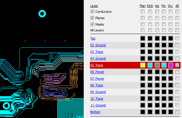
When in Layer Select Mode, any combination of multiple layers to be selected and viewed using CTRL+Layer to select.
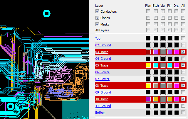
Trying to find routing channels for those last few hard to get in connections?
Use the power of Layer Select Mode to help you!!
4: FbQ & Multiple Copper Shapes
We improved dynamic shape parameters to enable users to select multiple shapes and view, edit or assign parameters, which will then apply the changed settings to each shape. Users also have the option to reset all parameters to the Global Default settings with a single click. Using SHIFT or CTRL + Click to select multiple shapes, performing a RMB in QIR 1 gives users an enhanced “Parameters” selection (as shown on the right screen shot – the left screen shot is pre-QIR 1.
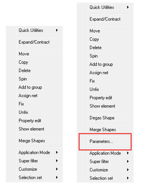
The Parameters dialog for multiple selected shapes has been enhanced to indicate the information that is different between the selected shapes and what settings have been changed from the Global Shape Parameters settings.
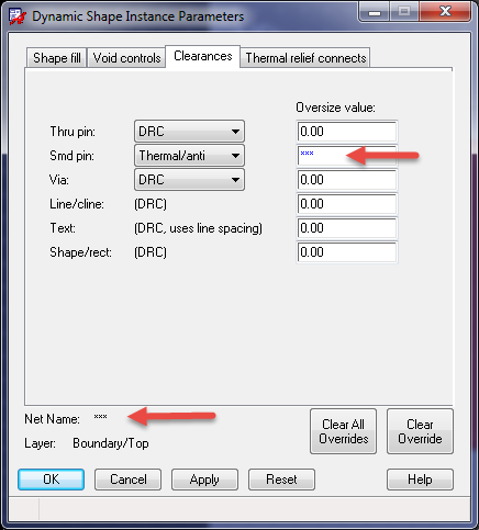
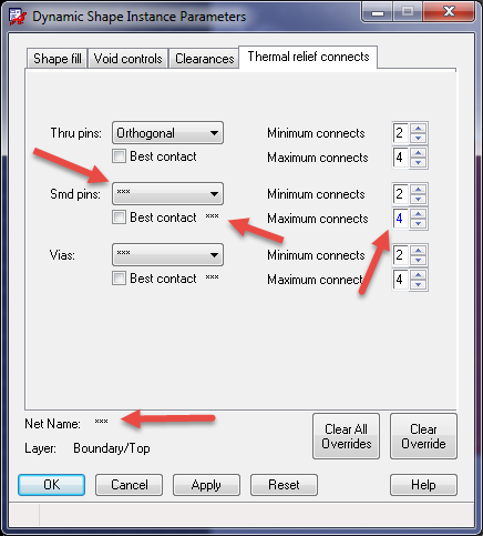
But the real hidden power of this new feature is to combine it with the power of FbQ – which we discussed earlier in this blog. Simply use FbQ to isolate the required copper planes, select those planes from within the Matching Objects pane and then use the RMB to access the Parameters dialog. Make the necessary changes and apply them to all of the selected copper shapes at once.
How easy is that?!
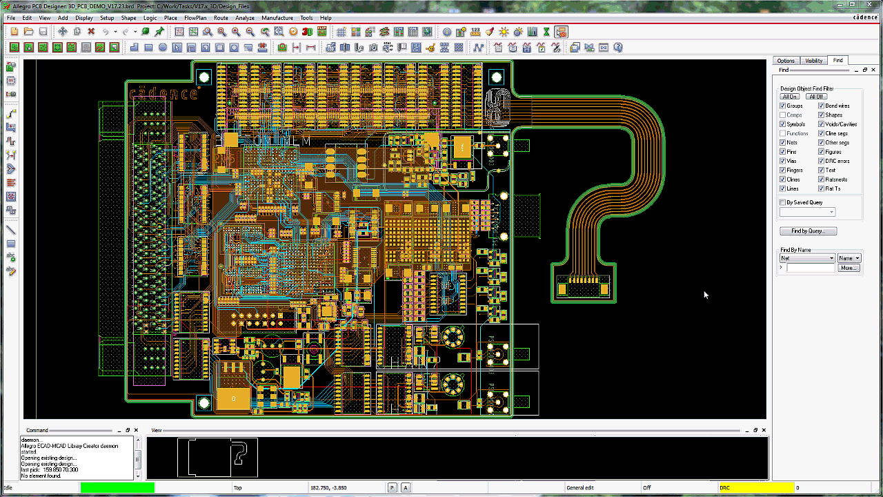
5: FbQ & 3D Canvas
Another feature that the power of FbQ can be harnessed to promote is the new 3D Canvas. This new 3D Canvas has taken our previous 3D Viewer and added intelligence. Additionally, unlike some other tools that make designers function either ONLY in the 2D space or the 3D space – but not both at the same time – we have re-written the 3D Canvas so that it can be visible, functioning and even more surprising to some – communicating with the 2D canvas.
If you find this intriguing, stay tuned for a future dedicated blog on our new 3D Canvas. In the meantime, allow me to once again demonstrate how two very different features of Cadence editors can be brought together to make the power of two even more productive for designers.
Using FbQ designers can easily select any critical routed traces and then invoke the 3D Canvas to review those routed traces in 3D. See them traverse layers and see them with their attached pads and pin padstacks. How cool and beneficial is that? You can do the same thing with components – either from within the PCB Editor canvas or from within the Symbol Editor tool. Now users can take advantage of the 3D canvas to visually confirm that their components are created correctly.
We hope you have found this blog helpful. Please check back periodically as new and related blogs will be added by our very experienced and resourceful team.
Originally published on cadence.com