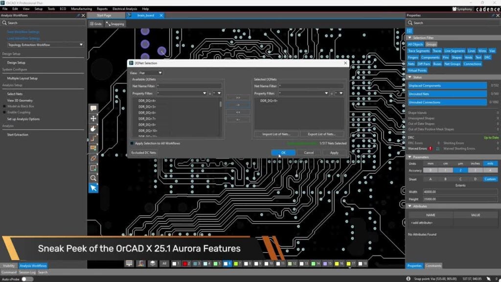
Sigrity Aurora enables signal and power integrity analysis in the familiar OrCAD and Allegro design environment to achieve an analysis-driven PCB design flow. In the previous video, we have extracted a topology from Sigrity Aurora. In part 3 of this video series, we will examine the topology and discuss:
- The topology extracted
- How to add more circuit elements
- How to edit component parameters
- Why driver and receiver pairs are important to run the simulation
In this video, you will learn:
- An overview of the Topology Explorer GUI
- The importance of a driver/receiver pair
- How to add additional components in topology
- How to edit parameters
Download the demo files to follow along here.
This video is part 3 in a 5-part series:
- Topology Explorer Part 1: Design Setup for Topology Extraction in Sigrity Aurora 17.4
- Topology Explorer Part 2: Topology Extraction and Controller Model Assignment
- Topology Explorer Part 3: TopXp GUI Overview and Adding Circuit Elements for Simulation
- Topology Explorer Part 4: Adding a SPICE Model and Lossy Transmission Lines
- Topology Explorer Part 5: Source Synchronous Topology and Sweep Simulations
For step-by-step instructions on how to use the workflows included in Sigrity Aurora, view our free workshops at EMA Academy.