EMA Resources

Blog

Home > EMA Resources > Blog > Essential Differential Pair Routing Guidelines

Essential Differential Pair Routing Guidelines

Following differential pair routing guidelines is essential for good signal quality for intraboard communications like PCIe slots

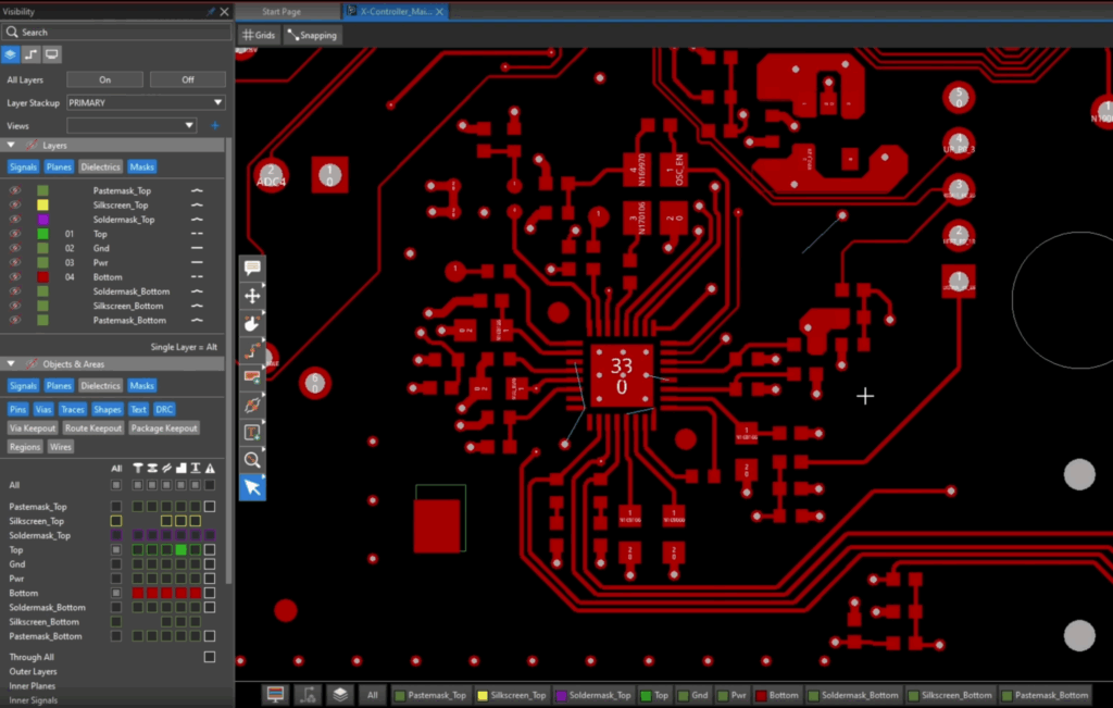
One of the most difficult tasks for PCB designers is laying out the board. Finding the optimal location for components and traces is also the most time-consuming. These challenges are multiplied for dense boards and/or when there are high trace counts, such as with PCIe intraboard communication. For these and other use cases, following differential pair routing guidelines is essential.  

Differential Pair Routing Essentials

Engineers usually have several routing topologies in their tool bag. However, there is often a more basic choice to make: Should single-ended or differential signal routing be used? In many cases, input-output requirements and board density dictate that differential pairs be used. In these cases, it is critical to follow differential pair routing guidelines, as listed below. 

IMPORTANT DIFFERENTIAL PAIR ROUTING GUIDELINES

Guideline

Why It’s Important

Make sure impedance is constant along traces

Impedance matching is critical for differential signal propagation. For maximum power transfer, the source impedance must match the load impedance (resistances equal in magnitude and reactances equal and opposite in polarity) and the characteristic impedance of the line must match the load impedance.

Use the same copper width for each pair trace

Material differences between traces translate into impedance mismatch.

Keep pair trace lengths equal

Unequal traces will create reflection along transmission lines, which degrades transmitted signal strength.

Maintain equidistance between traces

Spacing is critical for impedance matching and to avoid signal degradation and/or reflections.

Isolate differential pairs from other traces

Keeping differential pairs adequately spaced from other traces minimizes or eliminates potential coupling that can introduce or increase electromagnetic interference (EMI).

Avoid routing around other board elements

Routing around components, via annular rings, or other board elements makes it difficult to keep trace lengths equal. Often, techniques like meandering–which may be limited to specific angles–must be deployed which may introduce some mismatch.

Use broadside routing for adjacent layer traces

For high-density boards, it is often necessary to run differential pairs on inner layers through vias. Doing so often requires adjusting return path voiding to maintain impedance balance. 

As this list indicates, symmetry is critical for routing differential signals. As this can be challenging, it is important to know when these guidelines should be employed.

Should You Use Differential Pairs?

As mentioned, trace routing can be predisposed due to external connections and/or space limitations. Nevertheless, it is important to know the advantages and disadvantages of differential trace routing. 

AdvantagesDisadvantages
  • Good common mode noise rejection ability
  • Yields a better signal-to-noise ratio (SNR)
  • Ground plane usage is typically minimal
  • Requires more surface space than single-ended traces
  • Trace routing mismatch can create significant signal integrity issues
  • Trace length and impedance must match

Clearly, there are signal integrity benefits to using differential pairs in your PCB layout. Yet doing so does necessitate that you are able to implement differential pair routing guidelines, which can be a challenge. 

Ensuring Differential Pair Guidelines Are Met

Your ability to satisfy the requirements for differential pair routing–at least, within a reasonable design and development time interval–is virtually proportional to the quality of the PCB design software tool(s) you use. 

How to Best Employ Differential Pair Routing Guidelines

There are significant advantages to differential pair routing and with the right software you can ensure your design achieves these benefits.

EMA Design Automation is a leading provider of the resources that engineers rely on to accelerate innovation. We provide solutions that include PCB design and analysis packages, custom integration software, engineering expertise, and a comprehensive academy of learning and training materials, which enable you to create more efficiently. For more information on essential differential pair routing guidelines to follow and how we can help you or your team innovate faster, contact us.
LinkedIn
Email

Table of Contents

Get Content Like This Delivered Directly to Your Inbox

Related Resources

EMA Design Automation