Modeling designs helps engineers verify whether their circuit will function as intended. Modeling programs simulate circuit behavior under different conditions and in accordance with the design requirements, allowing engineers to better plan and build circuits.
Every SPICE simulation needs to have a source or input signal. To analyze how the circuit will behave in real life, this input must be modeled accurately. If not modeled accurately, functionality issues can go undetected until far later in the design process, wasting time and money. To efficiently and accurately create a pulse source SPICE model, the intended input signal must be interpreted by identifying the type and signal values for replication.
What is a Pulse Source?
A pulse source creates bursts of current or voltage to generate step, pulse, square, ramp, sawtooth, reverse sawtooth, or triangle waveforms. These types of pulse sources are commonly required in transient circuit simulation.
What is Needed to Model a Pulse Source?
To create the required pulse source for simulation, there are three items that must be defined:
- Type
- Which type of signal will be the input for the circuit: voltage or current?
- Waveform
- What type of waveform will be used: Step, Pulse, Square, Ramp, Sawtooth, Reverse Sawtooth, or Triangular?
- Data Points
- What are the critical signal values to create the desired waveform: voltage/current levels, rise and fall time, etc.?
This information must be incorporated into the SPICE simulation model which can be achieved by manually creating or editing a text file. Keep in mind if the source signal created is not the intended outcome, values will need to be edited manually. This manual process to produce the desired source signal is time consuming and increases the likelihood of errors; however, the PSpice Modeling App provides a fast, easily-configurable, and fully-integrated method to create pulse sources for simulation.
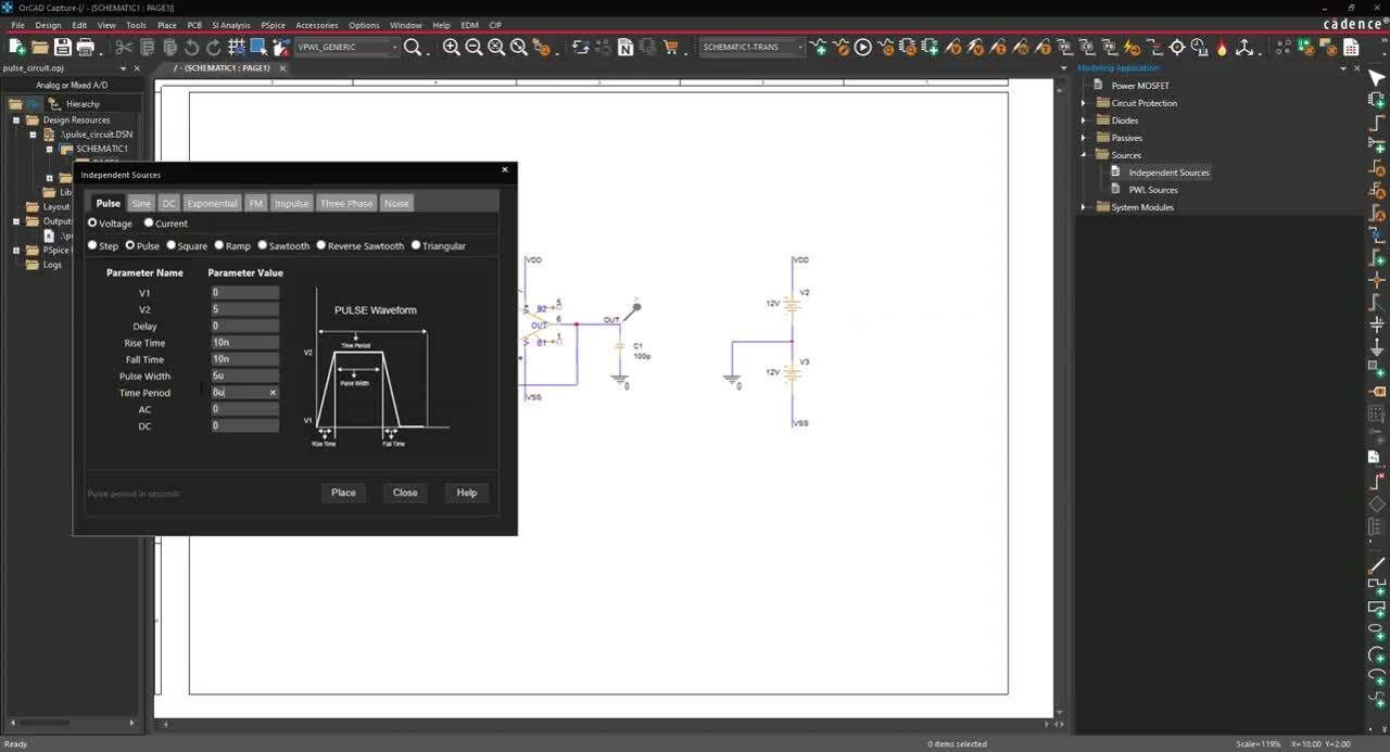
Creating a Pulse Source SPICE Model with PSpice
The pulse source modeling application quickly creates various pulse source models with a wizard-based approach. The necessary source specifications are pre-defined and users can easily input desired parameters required for all pulse sources such as:
- Source Type: Select either a Voltage or Current
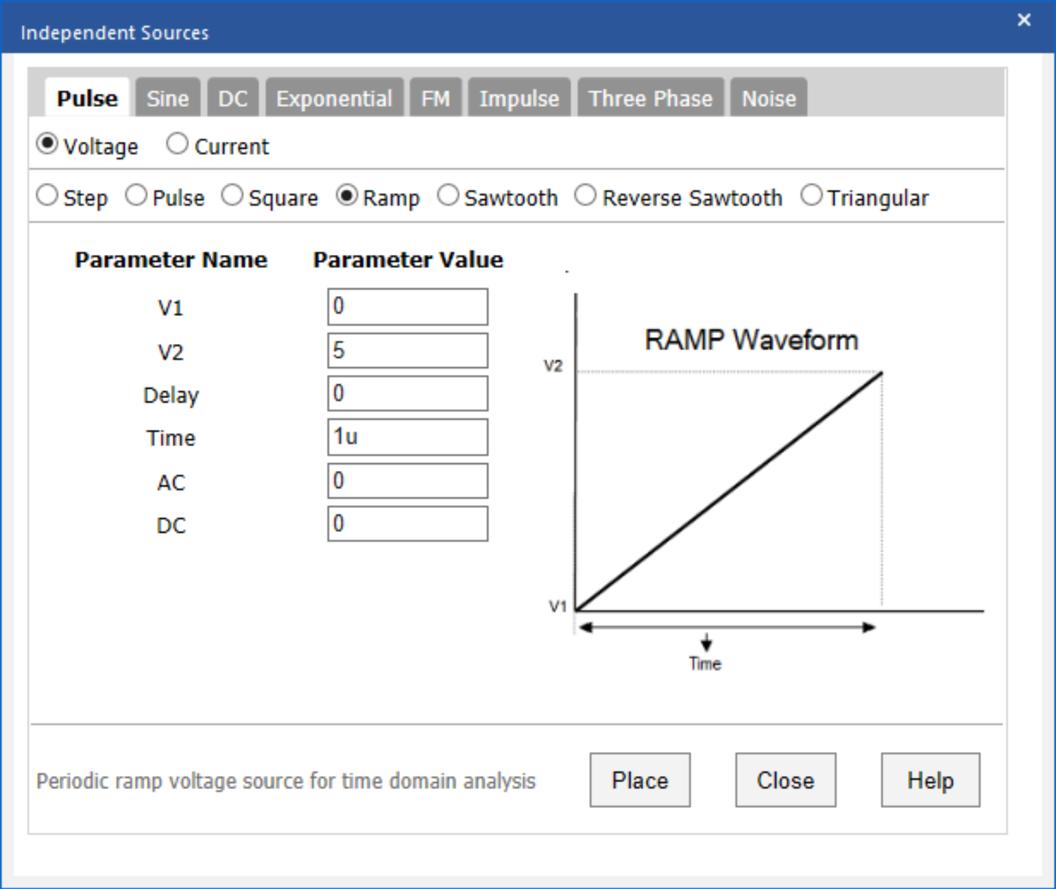
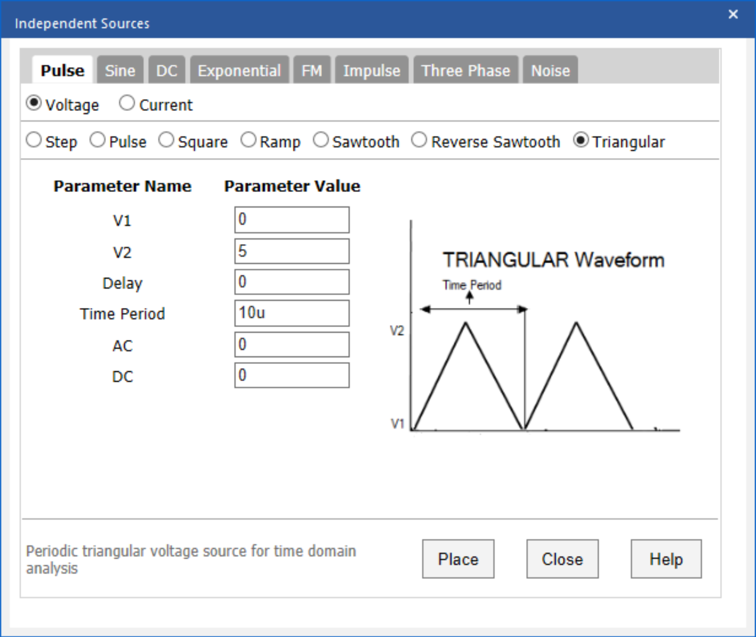
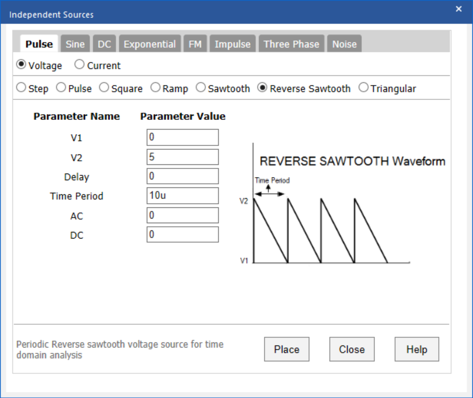
- Waveform Type: Select the desired pulse waveform type including step, pulse, square, ramp, sawtooth, reverse sawtooth, or triangular.
- Voltage or Current Levels: Quickly define the voltage or current levels needed for the pulse signal.
- Time/Time Period: Easily specify the time period or duration of the pulse.
- Delay: Quickly define a time delay for the pulse signal.
- AC and DC: Quickly specify the AC or DC voltage amplitude to be automatically added to source, achieving the intended AC sweep, bias point, or transient analysis.
Each waveform has a unique set of data requirements. The PSpice Modeling App takes away the guesswork with pre-defined templates customized for each waveform to include:
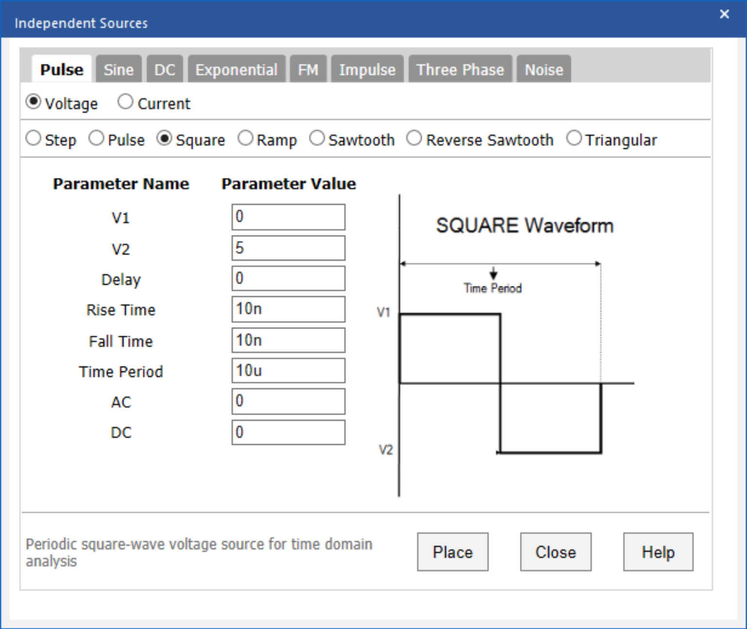
- Rise/Fall Time: For pulse and square waveforms, quickly specify the time it takes for the signal to increase from V1 to V2 and the time it takes for the signal to decrease from V2 to V1.
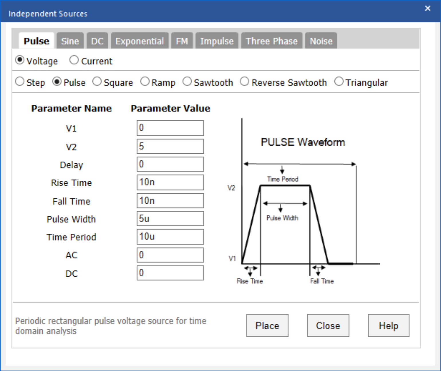
- Pulse Width: For pulse waveforms, easily define the width of the pulse
Using the inputted information above, the PSpice Modeling App generates a schematic symbol and automatically associates the newly created pulse source SPICE model without leaving the OrCAD Capture environment. The PSpice Modeling App also automatically manages the simulation profile configuration, eliminating any library set up for simulation.
To learn more, be sure to keep an eye out for additional SPICE model how-to’s in this series and get the step-by-step guide to create a Pulse Source SPICE model here.


