In previous versions of PSpice, example files could take a little bit of digging around to find. Now in 16.6, a new utility has been introduced to help new users learn about some simple circuits and easily pull up working examples.
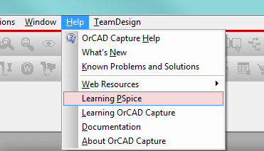
This utility is available in Capture by going to Help > Learning PSpice.
Once invoked, a new tab will open up with an Introduction panel on the left side and content on the right side. Presently, there’s only one section on Basic Electronics but this whole Learning PSpice dialog is based on HTML5 for extendibility with the purpose of adding a lot more content and examples in the near future.
Today there are a lot of examples which are useful to everyone from students looking to understand electrical concepts to professionals trying to understand how PSpice works. The examples are organized like this:
Theorems
- Ohm’s Law
- Kirchoff’s Voltage Law
- Kirchoff’s Current Law
- Thevenin’s Theorem
- Norton’s Theorem
- Superposition Theorem
- Millman’s Theorem
RLC circuits
- RC circuits
- AC circuits
- RL circuits
- RLC circuits
AC Circuits
- RC Circuit
- RL Circuit
- RLC Circuit
Three phase circuits
- Star connection
- Delta connection
Diodes
- Biasing
- Clippers
- Clampers
- Zener diode
- Zener Regulator
BJT
- Common Base configuration
- Common Emitter configuration
- Emitter follower
- BJT as Switch
- BJT as an amplifier
Operational amplifiers
- Inverting Amplifier
- Non-inverting Amplifier
- Differential Amplifier
- Voltage Follower
- Adder
- Subtractor
- Integrator
- Differentiator
- Active Peak Detector
- Precision Rectifier
- Linear Current Source
- Zero Cross Detector
- Simple Oscillator
- Wien Bridge Oscillator
- Schmitt Trigger
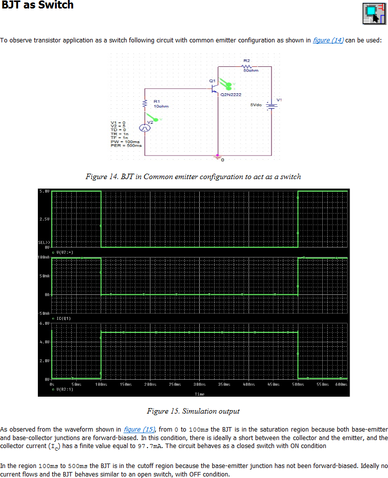
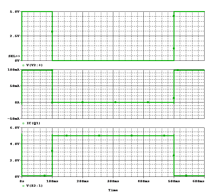
To learn some more, we’ll take a look at the example of using a transistor as a switch (Basic Electronics > BJT > BJT as Switch). In this example, you can see the schematic at the top, the resulting waveforms below and an explanation of the expected behavior at the end.
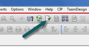
What you don’t want to miss is the Capture schematic icon in the upper right hand corner

By clicking on this icon, the tool will open up the same example for you to experiment with in Capture.
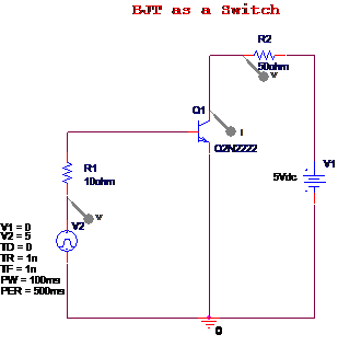
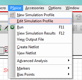
At this point, all you need to do is choose PSpice > Run, or hit F11 or the Run icon

to have PSpice calculate the result and verify that it looks like what’s in the Learning PSpice utility.
As you can see, this is a really quick way to learn some basic electronics principles and also how to use PSpice to observe them. Be sure to poke around and look at the part’s properties (double click on any part) and the Simulation Profile (in Capture, PSpice > Edit Simulation Profile) to see how everything was set up.
Thanks for reading—take a look at the Learning PSpice utility today!


