Wouldn’t it be nice if you could visualize your board and its enclosure in 3D from within OrCAD PCB Editor to ensure proper fit? Would you like to be able to see and approve proposed changes from the mechanical team before they are committed? Now you can. OrCAD PCB Editor 16.6 Update #2 provides a complete path for a collaborative, bi-directional ECAD/MCAD design flow.
Then and Now
Prior to release 16.6 OrCAD PCB Editor supported 2D and simple extruded 3D CAD data exchange with DXF, and IDF 3.0. This process worked and could get the job done, but it did not provide true collaboration. Release 16.6 has added full 3D visualization and incremental MCAD/ECAD collaboration with support for two new data formats; STEP and IDX.
3D Visualization with STEP
STEP models are CAD files that describe graphical detail for a physical part. STEP is a very common format in the mechanical world and is supported almost universally within the MCAD tool suites making it an ideal choice to transfer 3D graphical data between the ECAD & MCAD domains. OrCAD 16.6 allows users to import and visualize both electrical and mechanical (enclosure, fans, heatsinks, etc) elements.
Examples:
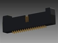
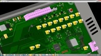
STEP support gives the designer the ability to see a realistic three dimensional representation of the design in the context of the enclosure and/or other physical limitations they must account for. Within this 3D environment it is easy to perform visual clearance checks to detect clashes early on and ensure you will have proper fit when you move to manufacture.
OrCAD also allows the designer to package the board up as a single STEP file that they can then send to the mechanical team for use in their 3D environment (check out the STEP Support video here).
On its own STEP support provides a huge improvement in the ability for the PCB designer to account for mechanical requirements and share completed design data with their mechanical counterparts. However, STEP is not ideal when working iteratively or evaluating trade-offs between mechanical and electrical changes as it does not provide a mechanism to manage change requests or history.
To handle a more iterative and collaborative design flow the ProSTEP iViP Association (same governing body that manages the STEP format) created IDX.
Incremental Collaboration with IDX
Often times the mechanical and electrical teams will tend to work in isolation sharing data only at the beginning and end of the development process. Meanwhile both teams are working diligently on their areas of responsibility making updates, and placement changes to meet their individual design objectives. Often these changes are made without consideration of the effects they would have on the other party. As these changes pile up over the course of the project this can lead to significant and unnecessary re-work once the electrical and mechanical teams synch up again.
IDX solves this problem by allowing the mechanical and electrical design teams to collaborate on design changes early and often, right from within their native tools. When either the mechanical or electrical teams make changes that could impact the other they can quickly generate an IDX update which provides a list describing the changes along with any descriptive comments.
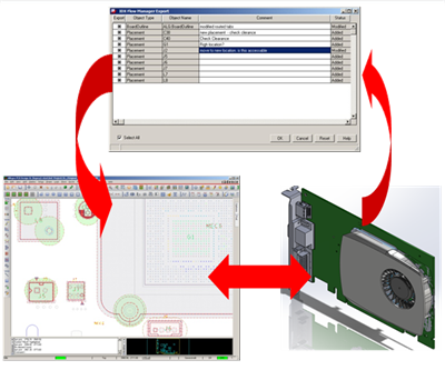
In OrCAD PCB Editor the PCB designer can than cycle through the list reviewing the changes and their potential impact. The IDX change list dialog cross probes directly with the editor canvas so you are able to zoom in to each change as you review them. The designer then has the ability to accept or reject each change and send their approval (or lack thereof) back to the mechanical designer, along with any comments.
IDX will keep a full historical record of changes so teams can review change history along with the comments as to why previous changes were deemed necessary or rejected.
The ability to perform these quick incremental synchronizations between MCAD and ECAD can pay huge dividends when concurrent design teams are working within tight contraints. The methodology behind IDX makes it easy for MCAD and ECAD teams to remain in sync throughout the entire design process. Design changes like part substitutions or mounting hole changes aren’t a surprise at the worst time, but instead are communicated as soon as they occur. This minimizes the impact of the change and allows teams to evaluate and react to changes early in the design process.
Full 3D Bi-Directional ECAD/MCAD Flow
With support for both STEP and IDX OrCAD 16.6 provides a complete collaborative ECAD / MCAD design flow, helping the PCB designer to visualize their design in 3D within the context of the mechanical enclosure as well as communicate design changes effectively between the ECAD and MCAD teams.
Stay tuned for future articles where we will go into more detail on how to use STEP and IDX in your OrCAD design flows.
As always we are interested in your comments and feedback.


