Prior to the development of the systematic PCB manufacturing process, which is based on an understanding and implementation of design for manufacturing and assembly or DFMA rules and guidelines from your contract manufacturer (CM), designing and building circuit boards were often combined into a single mostly manual process. However, innovations in manufacturing equipment and techniques have resulted in highly mechanized board fabrication and assembly. Coupled with these manufacturing improvements has been the development of software programs to help engineers design PCBs more reliably and efficiently.
The use of software for circuit board design is known as electronic design automation, which can be defined as follows:
Definition:
Electronic Design Automation of EDA, broadly encompasses the usage of software tools to develop or create electronic products, like integrated circuits (ICs) and printed circuit board assemblies (PCBAs). For PCBA development, this includes tools that influence all aspects of development: schematic design, board layout, simulation, verification and testing. |
To be competitive in the electronics industry today, it is important that you understand how electronic design automation is implemented, and the tools available to help you optimize your PCBA development process.
Electronic Design Automation Applications
Accurate data acquisition and system modeling are the foundations of effective electronic design automation. For example, specific MIPI standards models are required to perform circuit board design verifications, like compliance testing of MIPI boards, that are used in displays for everything from smartphones to automobiles to industrial systems. Other PCBA design applications where EDA is employed are listed below.
ELECTRONIC DESIGN AUTOMATION Applications for PCB Design | |
Applications | Implementations |
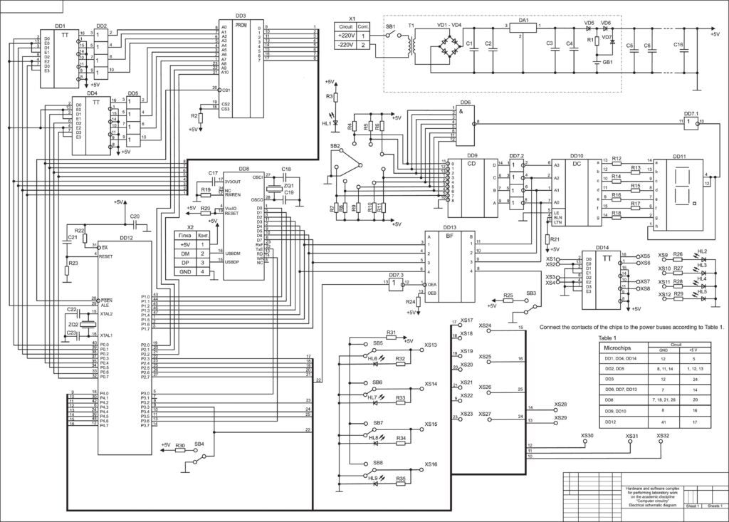
Schematic Capture | Component parametric evaluations, design rule checking (DRC) |
PCB Layout | Component placement, trace routing |
Circuit Simulation | Digital, RF and microwave signal analyses, power distribution network (PDN) evaluation |
Design Verification | DFM and constraint management, TX/RX timing verification, thermal distribution and dissipation analyses, compliance testing |
Data Management | Component CAD model libraries, engineering data management, product lifetime management (PLM) |
The list above is not exhaustive. Yet, it does demonstrate the degree to which electronic design automation can be leveraged to help improve the reliability of your PCBA design process. Other benefits of employing electronic design automation include the following.
Benefits of Electronic Design Automation for PCBA Development
- Faster new product development
- Reduced errors and redesign
- Keeping up to date with changes
- Supply chain issues like component availability
- Design changes like engineering change orders (ECOs)
- Reduced development costs and increased ROI
The need to maximize the reliability and efficiency of your design process has never been greater. Demands for smaller boards with ever-increasing capability, coupled with industry challenges like component shortages and supply chain bottlenecks, make optimizing your PCBA development process a necessity. And EDA tools are your greatest asset in meeting these challenges.
EDA Software Tools for PCB Development
There are many EDA software tools available. However, functionality, capability and usability can vary greatly. Therefore, it is important to define your PCB design process needs and align these challenges with the capabilities and design enhancements that an EDA tool should have to meet your needs. Some of the best EDA software tools, based on PCB design implementation, are listed below.
PCB Electronic Design Automation Tools
PCB Design can be broadly divided into two major stages: schematic capture and PCB layout design. Improving one or both of these activities is the objective of electronic design automation. EDA software programs perform real-time DRC, schematic-PCB synchronized component placement, interactive routing, in-design analysis, and more advanced functions, as listed below.
💻 Advanced Schematic Capture and PCB Layout EDA Tools
- PSpice
Extensive component/module/board simulation and analyses. Including time and frequency domain analyses, component stress testing, worst-case scenario evaluations, electrical/mechanical simulation, etc.
- Sigrity
Signal and power integrity (SI/PI) analyses, electromagnetic interference/electromagnetic compatibility (EMI/EMC), TX/RX channel analyses, etc.
- AWR
RF/microwave communication system analyses, DRC, layout vs schematic (LVS) analysis, etc.
- Celsius
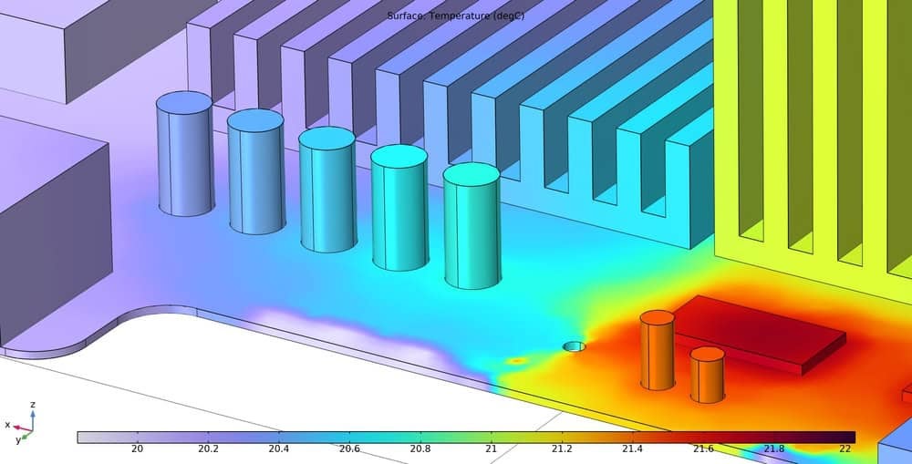
Thermal and cooling analyses, ECAD/MCAD integration, what-if analyses, etc.
- TimingDesigner
Component, package, PCB and system timing analyses.
- EDM software
Automatic revision control, design synchronization within and across teams, user management, file and design library management.
One of the most important aspects of EDA software tool utilization is ensuring that your solution integrates with other software that you use. To ensure smooth integration, it is probably best to partner with an industry leader with a track record of providing successful EDA software solutions for engineers.
EMA Design Automation is a leading provider of the resources that engineers rely on to accelerate innovation. Based on decades of engineering expertise, we provide solutions that include cutting edge PCB design and analysis packages and customized integrations to help you optimize your electronic development workflow and create more efficiently. For more information on effectively using electronic design automation and how we can help you or your team innovate faster, contact us.


