 A wire harness is a solution for maintaining the organization of multiple wires or cables. It is a cohesive configuration of cables encased within an insulating material, facilitating the transmission of data signals or electrical power. This encompasses a wide range of applications, from CAN bus systems for vehicles and aircraft, medical devices, telecommunications infrastructure and renewable energy installations. For this reason, the wire harness assembly process is important in ensuring the reliable operation for specific environmental, electrical, and spatial requirements of each application.
Wire Harness Assembly Process
Notes on Wire Harness Assembly Process Automation
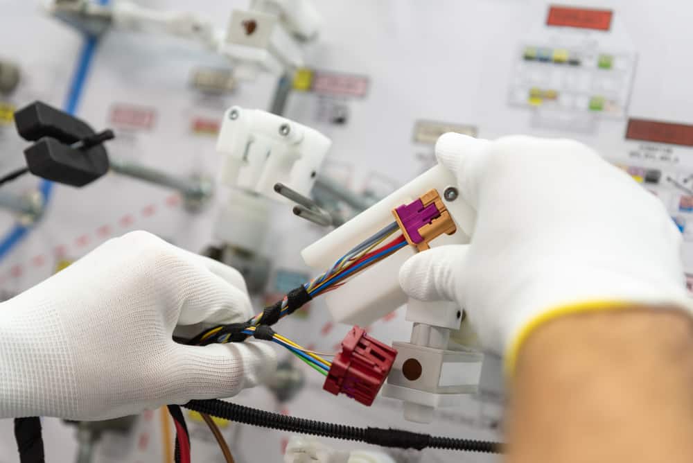
In today’s world of automated PCB manufacturing, it’s worth noting that the wire harness assembly process still continues to depend on manual labor. Despite the potential for some degree of automation, the intricate nature of assembling wire harnesses and cable assemblies necessitates a hands-on approach. Crafting a wire harness involves numerous detailed and time-consuming tasks, making manual assembly not only necessary but also more cost-effective in many cases. Furthermore, the need for manual production in the creation of wire harnesses and cable assemblies is a result of their inherent need for customization. Wire harnesses are highly specialized components tailored to fit specific applications and larger systems and thus require manual craftsmanship in their assembly.Manual Labor Requirements in the Wire Harness Assembly Process
Manual labor plays a key role in wire harness production, especially for:- Threading wires through sleeves
- Applying fabric tape at necessary points like branch-outs
- Crimping terminals onto wires. When a single terminal must connect to multiple wires, multiple crimping operations are required
- Inserting sleeves into each other
- Securing wire strands with tape, clamps, or cable ties
Automation Use in The Wire Harness Assembly Process
While hand production is essential, it doesn’t completely exclude the use of automation and machinery in the manufacturing process. For instance:- Cutting machines are employed to cut wires to exact lengths
- Machines are utilized for crimping terminals or partially inserting wires with fitted terminals into connector modules
- Soldering machines seal wire ends
- Tools are used for twisting the wire
The Engineering Behind Wire Harnesses
- Engineers calculate the required gauge (thickness) of wires based on the current they need to carry and the length of the wire to minimize voltage drops and power losses. The layout must also consider the potential for electromagnetic interference (EMI), ensuring that sensitive signals are shielded or routed away from power lines to prevent cross-talk and interference.
- Conductors are typically made of copper or aluminum, chosen for their excellent electrical conductivity and flexibility.
- Insulation materials, such as PVC, polyethylene, or Teflon, are selected based on their electrical insulation properties, resistance to heat, chemicals, and UV light, as well as their mechanical durability.
- Protective sleeving adds another layer of protection against abrasion, moisture, and thermal extremes.
- Crimping, which involves deforming a metal connector to tightly grip a wire, relies on understanding material deformation and applying precise force to ensure a strong electrical and mechanical bond without damaging the wire.
- Soldering, used in some connections, involves melting a filler metal (solder) to join metallic surfaces, requiring knowledge of solder flow, wetting, and thermal management.
EMA Design Automation is a leading provider of the resources that engineers rely on to accelerate innovation. We provide solutions that include PCB design and analysis packages, custom integration software, engineering expertise, and a comprehensive academy of learning and training materials, which enable you to create more efficiently. For more information on the wire harness assembly process and how we can help you or your team innovate faster, contact us.