A voltage-controlled oscillator (VCO) is a type circuit where the output frequency can be adjusted or varied through a DC input voltage. Often referred to as a voltage-to-frequency converter (VFC), this circuit can produce output waveforms such as sine, square, or various other shapes, with the specific waveform being determined by the design of the circuit. Here, we’ll be discussing methods for effective voltage control oscillator design.
Specifying VCO Design Parameters
Effective voltage control oscillator design is achieved by employing effective modeling and simulation. In order to employ this design methodology, it is important to understand the defining parameters listed below.
Discrete, Modular and Monolithic VCOs
Voltage-controlled oscillators (VCOs) are available in various forms, including discrete, modular, and monolithic configurations.
- Discrete voltage control oscillator designs offer exceptional customization flexibility, making it a popular choice for do-it-yourself (DIY) projects. They are typically based on established oscillator topologies, such as Hartley and Colpitts inductor-capacitor (LC) oscillators. This design approach allows for tailored specifications to meet the unique requirements of various applications, emphasizing the versatility and adaptability of discrete VCOs in the field of electronics. We’ll be discussing discrete voltage control oscillator designs in the upcoming sections.
- Modular voltage-controlled oscillators (VCOs) are more integrated —Encased in compact modular units, these VCOs function similarly to individual components.
- Monolithic VCOs are developed as monolithic integrated circuits (ICs), which achieve the highest level of volume density.
VCO Output Types
VCO outputs may be classified according to oscillator function, as linear or harmonic, or relaxation.
- Linear or harmonic oscillators are known for their ability to produce a sinusoidal waveform. These oscillators typically involve a resonator coupled with an amplifier. The amplifier’s role is to compensate for the losses within the resonator, ensuring the amplitude remains constant, and to shield the resonator from the output, preventing the load from influencing the resonator’s performance. LC oscillators and crystal oscillators are prominent examples of harmonic oscillators.
- Relaxation oscillators are designed to produce sawtooth or triangular waveforms and are frequently utilized within integrated circuits (ICs). The op-amp design we have examined is an example of these. These oscillators are prized for their ability to offer a broad spectrum of operational frequencies, while requiring a minimal assortment of external components.
Examining a Basic Voltage Control Oscillator Design
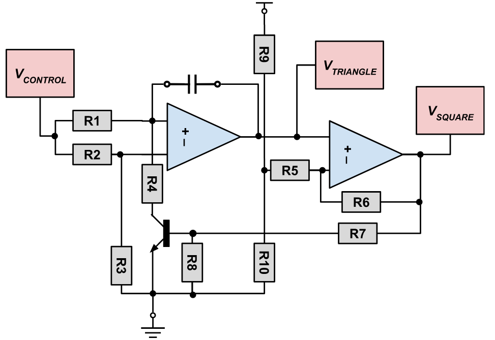
Voltage controlled oscillator design with triangle-wave output made from charging cap and op-amps
Below is a breakdown of the voltage control oscillator design shown in the image. This is an example of a discrete design, and there are many many more variations that can be done with op-amps.
- The circuit operates based on the principles of an ‘integrator/comparator’. It incorporates a capacitor, as part of the integrator, which is built around an operational amplifier, A1 (on the left). This capacitor is charged by a constant current source, the magnitude of which is set by the current level of the control voltage applied.
- Consequently, the output voltage of A1 decreases in a linear manner. Once the output voltage reaches the lower threshold set by the comparator (constructed with A2 op-amp on the right side), the state of the comparator’s output changes, causing the transistor to start conducting.
- At this juncture, the capacitor is quickly discharged, leading to an increase in A1’s output voltage. This increase also follows a linear trajectory. This process is cyclical, with the cycle repeating itself. When the output of A1 reaches the upper threshold of the comparator, T1 is turned off.
If resistors R2 and R3 are set to the same value (R2 = R3), and resistor R1’s value is double that of R4 (R1 = 2 x R4), the resulting duty cycle of the output voltage’s controlled frequency will be 50%. The levels of the triangular DC output voltage are dictated by the values of resistors R9 and R10. Based on the values of R9 and R10 as specified in the schematic, the triangular DC level will typically be half of the supply voltage.
Frequency Control Methods
Below is a summary of frequency control methods for voltage control oscillators.
- Using a voltage-controlled capacitor is a common technique to adjust the frequency of an LC oscillator based on a control voltage. This approach leverages the fact that semiconductor diodes exhibit a capacitance that varies with the applied voltage when reverse-biased. By altering the control voltage applied to such a diode, one can effectively change the frequency of an oscillator. Specifically, varactor diodes, which are designed for this purpose, offer a wide range of capacitance values that are well-documented, making them ideal for tuning the capacitance—and consequently, the frequency—of an LC tank circuit.
- Varactors can also adjust the loading on a crystal resonator, thereby shifting its resonant frequency.
- For VCOs operating at lower frequencies, alternative frequency variation methods are utilized, such as modifying the rate at which a capacitor charges through a voltage-controlled current source (a technique often seen in function generators).
- The frequency of a ring oscillator is modulated by altering the supply voltage, the current supplied to each inverter stage, or the capacitive loading on each stage.
- A voltage-controlled crystal oscillator (VCXO) can be used to finely adjust the operating frequency. The tuning range of a VCXO is limited to a few tens of parts per million (ppm) across a control voltage range, typically from 0 to 3 volts. This limited range is due to the high quality (Q) factor of the crystals, which allows for frequency modulation over only a narrow frequency spectrum.
Understanding the parameters, circuit functionality types and configurations are important for voltage control oscillator design. However, the best way to efficiently explore operational characteristics and ensure voltage stable design is by modeling and simulation. Equipped with the best circuit simulation software, you can design circuits of all scales that achieve the precision and performance your product demands. To learn more about optimizing circuit simulation, see this eBook on Advanced SPICE Analysis.
EMA Design Automation is a leading provider of the resources that engineers rely on to accelerate innovation. We provide solutions that include PCB design and analysis packages, custom integration software, engineering expertise, and a comprehensive academy of learning and training materials, which enable you to create more efficiently. For more information on voltage control oscillator design and how we can help you or your team innovate faster, contact us.