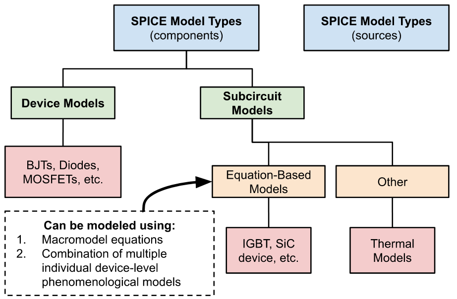
SPICE model types at the highest level fall into two categories: sources and components. Sources represent voltage or current sources within your circuit and can take various forms such as transient, piecewise linear, sinusoidal, pulsed, square, etc. They can be either dependent or independent within the models. On the other hand, components are elements that either receive input directly from a source or from the output of another component. The number of component SPICE model types is vast; however, there are well-defined methods for representing electronic parts for PSpice simulation and analyses.
SPICE Model Device Types Overview and Subcircuits Discussion
SPICE models use mathematical equations to simulate the output voltage or current based on a variety of inputs and model parameters.
Device models represent single individual components like diodes and MOSFETs, capturing electrical behavior through specific equations. These models identify the parameters (coefficients) used in the equations to characterize the electrical properties of transistors, diodes, or other devices.
Subcircuit models, on the other hand, are complex assemblies made up of various device models, serving as comprehensive representations of a circuit’s state. Moreover, special models are employed for conducting thermal analyses of circuits, assessing how heat affects their performance. This representation, often referred to as a netlist, encapsulates a schematic’s group of standard components. Such a subcircuit can be exported and subsequently assigned to a specialized component, enhancing the flexibility and customization potential in circuit simulations. This approach is instrumental in modeling complex components and systems within SPICE simulations.
SPICE Device Model-Type Examples
A device model typically consists of a declaration that includes the model name, type, and parameters associated with the device.
Diode SPICE Model Example
Despite the common portrayal of diodes as straightforward components, their internal structure is complex. For an accurate representation of their behavior, diodes require multiple SPICE model parameters. These parameters cover aspects such as breakdown voltage and current, saturation current, and lead resistance. Below is a summary of relevant SPICE parameters for a basic diode model.
Transistors
MOSFET and BJT transistors are modeled using either large-signal or small-signal models, depending on their operational regime.
- For small-signal operation, parameters describe the transistor’s behavior near the DC bias point, required for handling AC signals without causing saturation in collector/source current.
- Large-signal models are used for describing operations from the linear to saturation regions and require defining extensive parameters within a subcircuit. BJT transistors, for example, have 28 SPICE model parameters that account for behavior in both linear and saturation phases. Among these are material properties, temperature coefficients and zero-bias capacitances.
Spice Model Types: Subcircuit Models
Subcircuit models are representations of entire circuits (but can be used in larger circuits, thus the “sub” prefix). They include details about circuit connections, component models, and additional relevant data. These models integrate device models, power sources, and equations to simulate a circuit’s configuration accurately. They are composed of several component models and include key elements:
- Subcircuit declaration that specifies the model name and external connection pins
- Detailed circuit connections
- Device characteristics
- Unique identifier to mark the end of the subcircuit model description
Within these models, each connection is defined by:
- An instance name
- The specific connection pins associated with that instance
- Model name
Macromodels vs Device Level Simulation for Subcircuits: Op-Amp Example
When simulating circuits incorporating subcircuits, a macromodel approach can be used to represent each of them. Take for example an operational amplifier (op-amp). Op-amps are composed of many individual transistors. However, it can be modeled by a macromodel approach to save bandwidth and speed up simulation times:
- A macromodel approach relies on the observable characteristics at the terminals of the op-amp, rather than detailing each transistor within the op amp’s internal structure. Macromodels enable the development of accurate simulations based on the specifications provided in data sheets, without the necessity of understanding the intricate internal circuitry of the op-amp.
- A device-level approach would aim at modeling each individual transistor within the op-amp system, thus allowing for higher level of accuracy, at the cost of computer resources and time.
Equation Based Models: SiC Example
The SPICE model parameters for Silicon Carbide (SiC) MOSFETs are similar to those for large-signal transistors, but also incorporate specifics on channel geometry and essential material characteristics. The emphasis on material aspects, such as electron mobility and gate oxide thickness, is important due to the lack of a universal model for SiC MOSFETs.
For this reason, distinct models are required for SiC MOSFETs and Silicon Carbide-Gallium Nitride (SiC-GaN) MOSFETs, each demanding unique parameters. Given the novelty of these components, their representation through SPICE models remains an active area of research. Some SiC MOSFET manufacturers offer SPICE models for their devices, enabling users to simulate similar components by modifying the provided SPICE model files.
Other Subcircuit Examples
Components such as phototransistors, CCD arrays, ADCs (Analog-to-Digital Converters), and relays can be represented in simulations as either subcircuits or phenomenological models (also known as macromodel models). The choice between these modeling approaches hinges on the component’s complexity and the availability of detailed information in its datasheet necessary for constructing an accurate electrical model and simulation.
Optimizing SPICE Models in Your PCB Design
Whether you are newly learning PCB design or a seasoned expert, knowing how to effectively use SPICE model types, as shown below, to best use circuit design and simulation software is essential.
Guidelines for Using SPICE Model Types
- Understand SPICE model parametric structure
- Source SPICE models from a reliable source
- Use a SPICE model simulation software that integrates with your EDA tool
The best PCB CAD software programs include some form of circuit simulation functionality. However, for the most comprehensive and scalable SPICE model simulation solution, you should partner with an industry expert that can provide you with the best product design and support software with inherent advanced SPICE modeling capabilities or programs to expand the simulation and analysis capabilities of your EDA tool.
EMA Design Automation is a leading provider of the resources that engineers rely on to accelerate innovation. We provide solutions that include PCB design and analysis packages, custom integration software, engineering expertise, and a comprehensive academy of learning and training materials, which enable you to create more efficiently. For more information on SPICE model types and how we can help you or your team innovate faster, contact us.