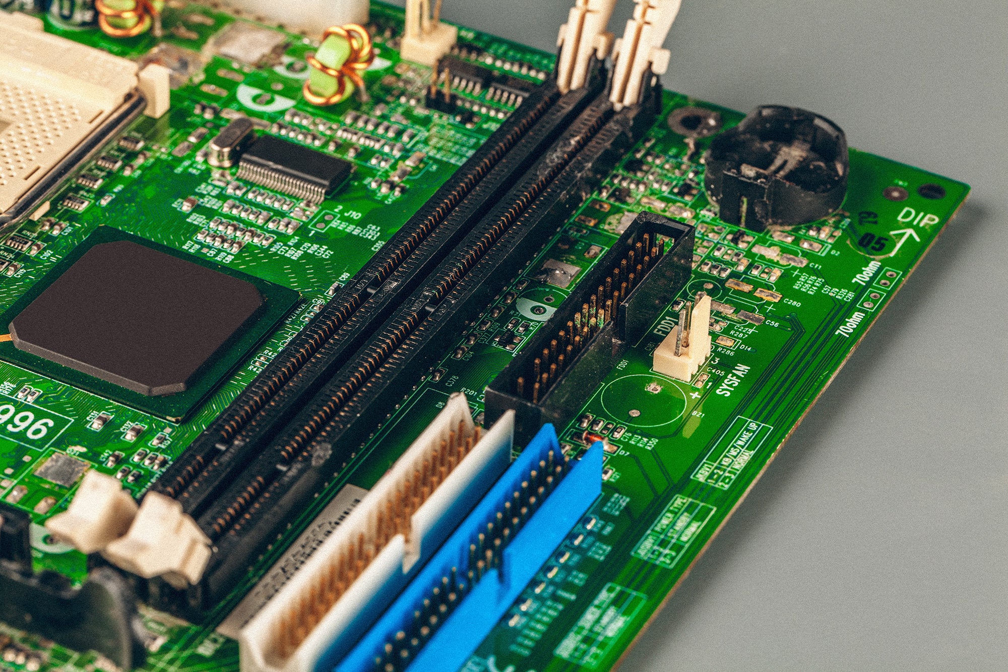
BlogPCB Layer Alignment Design GuidelinesMaster PCB layer alignment and PCB layer design: learn labeling,...See More
On-Demand WebinarsSigrity X: Reimagining Simulation Driven PCB Desig...Join the experts at EMA as we provide an overview...See More
How-ToHow to Quickly Generate Artwork Film RecordsLearn how to generate artwork film records required for a...See More
BlogEssential Differential Pair Routing GuidelinesKnowing and following essential differential pair routing guidelines is critical...See More
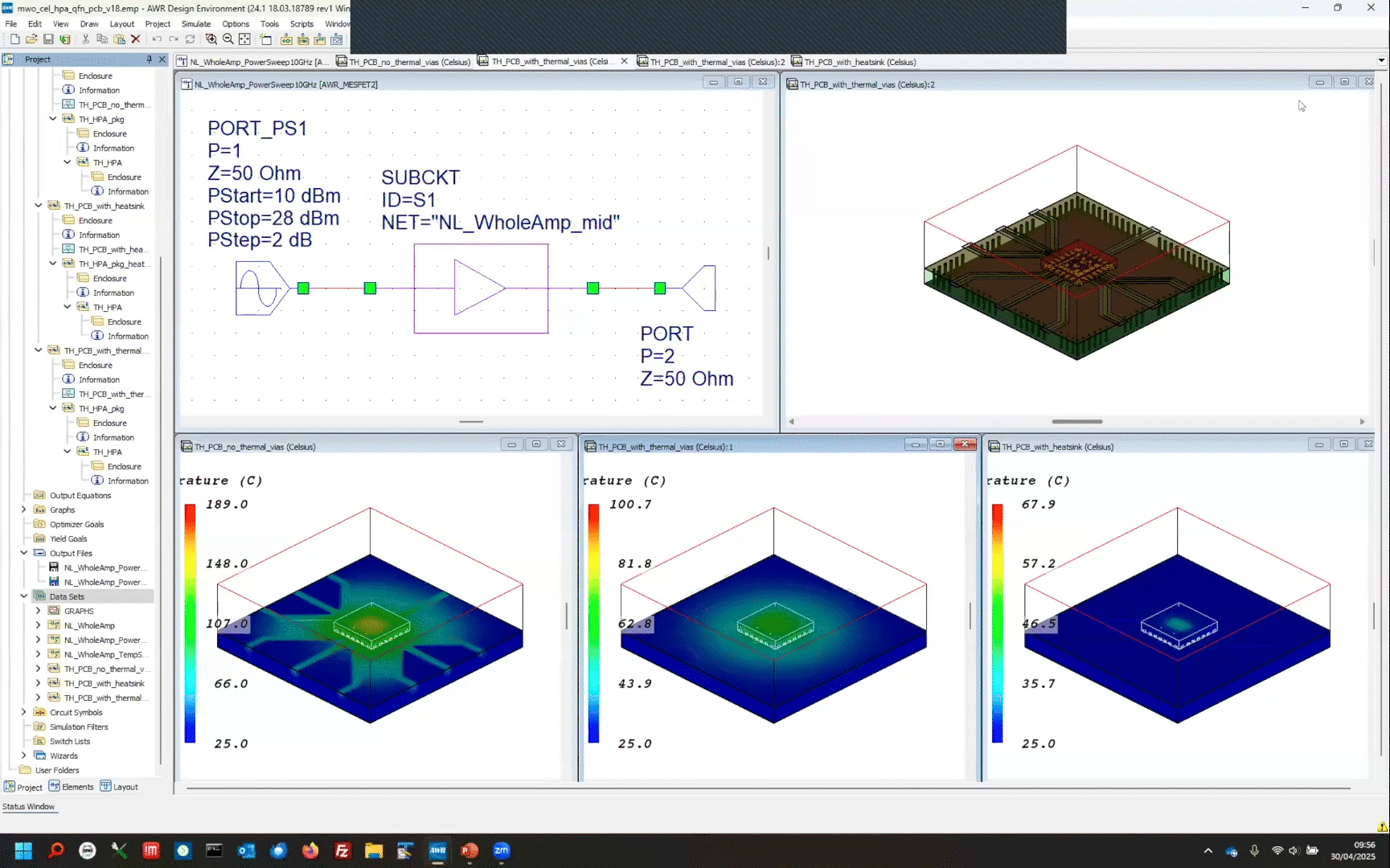
On-Demand WebinarsThermal Implications of Flip-Chip Technology for m...This webinar delves into the thermal and RF performance of...See More
On-Demand WebinarsHigh Speed Layout in OrCAD X – It’s Si...This 1-hour webinar will discuss efficient high-speed design practices that...See More
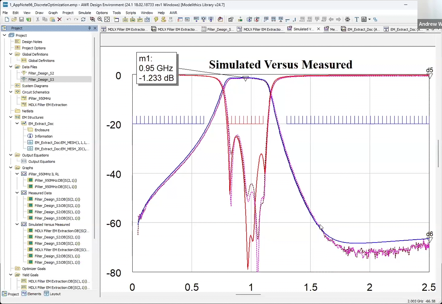
On-Demand WebinarsCadence TECHTALK: Enabling RF and MMWave Design Su...This webinar will discuss how to use Modelithics’ advanced models...See More
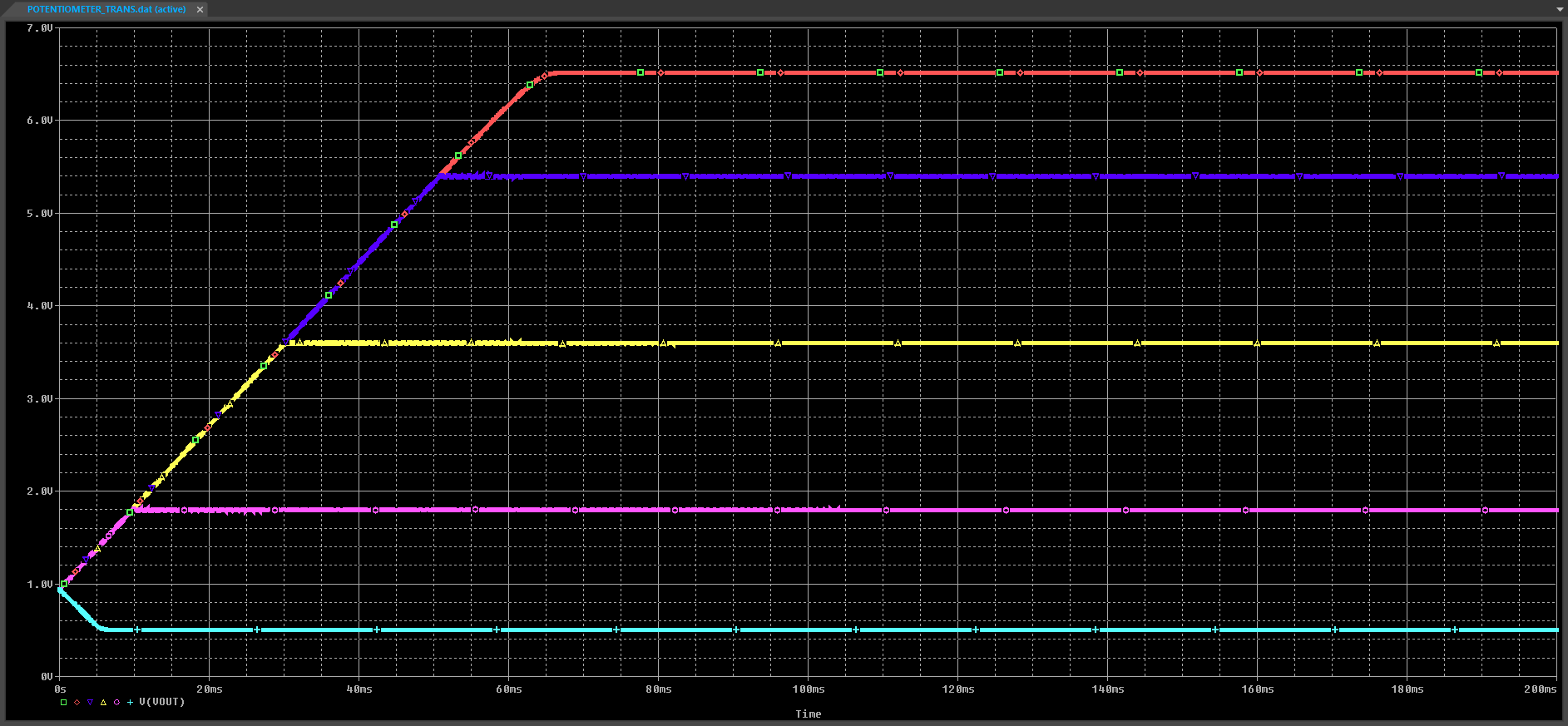
How-ToHow to Model a Potentiometer in PSpiceLearn how to model a potentiometer to accurately simulate a...See More
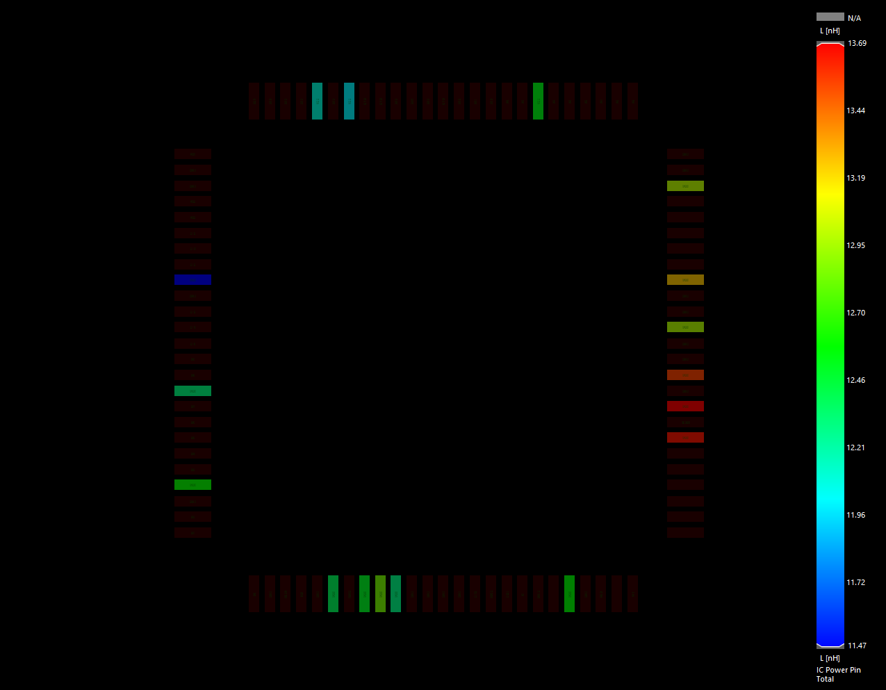
BlogInvestigating Loop Inductance: Understanding Impac...To ensure effective power delivery for your PCB designs, you...See More