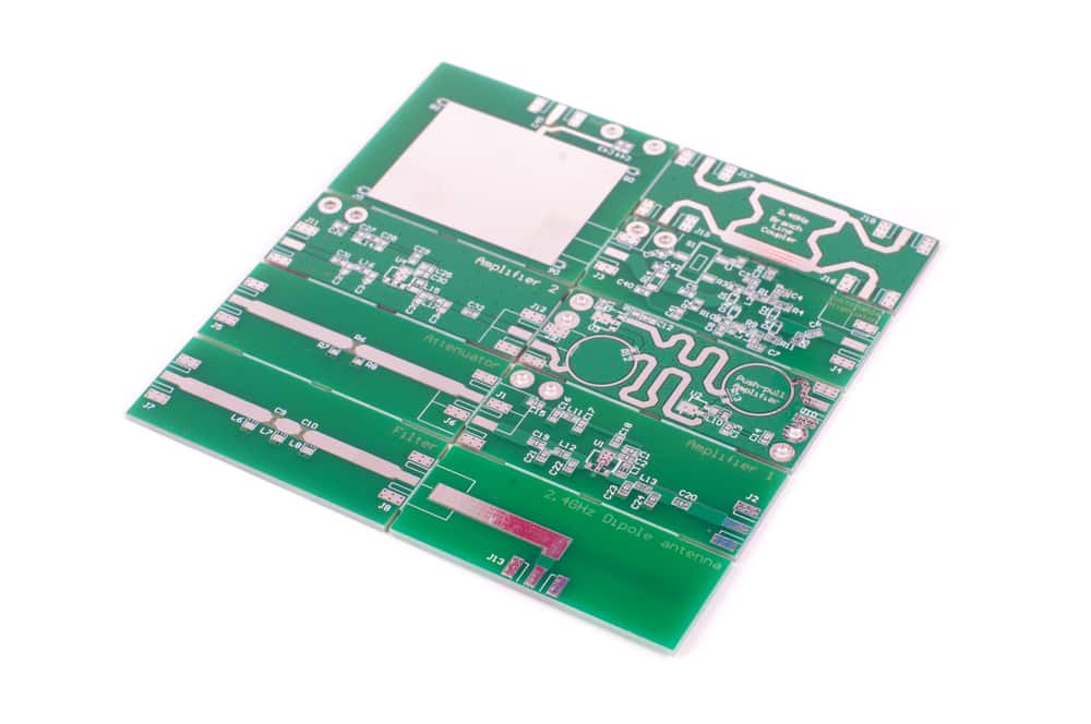
It is a common misconception that the shortest path is always the best course of action. Of course, this is based on a sound premise to minimize waste or loss. Interestingly enough, meandering, which is the intentional extending of a trace to ensure equal lengths of transmission line pairs, is an effective PCB routing method to minimize signal loss.
Reducing loss is a critical objective of PCB design for the best signal and power integrity. Achieving this goal depends to a great extent on your board’s impedances. Therefore, it is essential to know and implement important impedance matching techniques.
Impedance Matching Techniques to Know
The impact or effects of impedance, which can be defined as the opposition to the flow of electrons through an element based on its material properties, is an unavoidable consideration when designing electrical/electronic circuitry. Therefore, the goal for circuit design is to control the degree to which impedance adversely affects the flow of electricity. Doing so necessitates knowing important impedance matching techniques to employ.
Important Impedance Matching Techniques | |
Impedance Matching Technique | Why It’s Important |
Select antenna matching network design components such that source and load impedances are the same | To ensure maximum power transfer of signals to and from antennas. |
Use meandering or other routing techniques to ensure that differential trace pairs are identical in length | To reduce and/or eliminate reflections and signal degradation along PCB transmission lines. |
Keep trace routes separated according to creepage and clearance standard rules | To avoid reactive coupling and minimize EMI and help achieve EMC compliance. |
Avoid crossing split planes | To avoid and/or minimize impedance discontinuities. |
Choose stackup dielectric materials with a consistent impedance for multilayer PCB designs | Helps to maintain impedance matching between circuits and throughout the board. |
Minimize the number of vias for high-speed PCB design | To avoid and/or minimize impedance discontinuities and noise coupling. |
The above is not an exhaustive listing of PCB design decisions and actions that affect your board’s impedance. However, the techniques presented should be included, along with best practices like crosstalk reduction methods, as part of your PCB design strategy to ensure that your board is designed and built to maximize signal integrity (SI) and power integrity (PI).
Optimizing Impedance Matching for Your PCB Design
Knowing important impedance matching techniques and why they are important is essential. However, these methods are helpful only if implemented effectively, which can be achieved by following guidelines as described below.
Implementing Impedance Matching Techniques
|
Depending on your PCB CAD software and the complexity of your design, instituting many of the techniques above can be difficult, excessively time consuming and costly, or not available with your EDA tool. An effective option is to rely on an industry expert for circuit design and simulation software tools and design support materials to help you optimize your impedance matching techniques implementation.
EMA Design Automation is a leading provider of the resources that engineers rely on to accelerate innovation. We provide solutions that include PCB design and analysis packages, custom integration software, engineering expertise, and a comprehensive academy of learning and training materials, which enable you to create more efficiently. For more information on implementing impedance matching techniques to improve signal and power integrity and how we can help you or your team innovate faster, contact us.


