How do you know if a component will fail in your circuit? As the designer, it’s your job to ensure that the parts in your design are within their stress limitations. This can be tedious and time consuming, so shortcuts are usually taken. These shortcuts can range from not doing anything to only measuring certain components in your design that you feel are particularly stressed. This may lead to oversights which can manifest themselves as component failures in the lab or the field.
With Smoke Analysis in OrCAD PSpice Designer Plus, this component analysis becomes trivial, quickly yielding meaningful results. You can follow along with the RF Amplifier Design included in OrCAD (File > Open > Demo Designs > RF Amplifier)
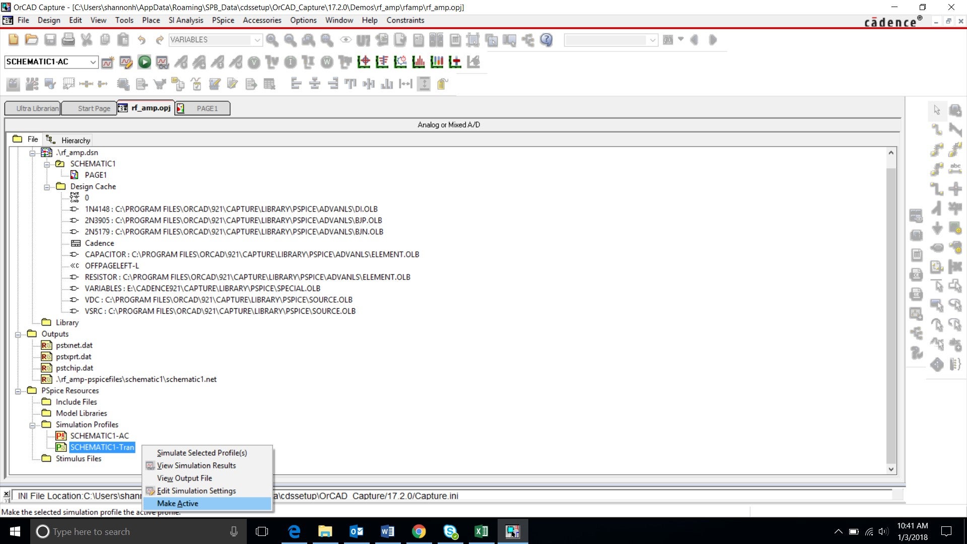
Step 1: In the directory tree, ensure the transient schematic profile is selected by right-clicking and choosing “Make Active”.
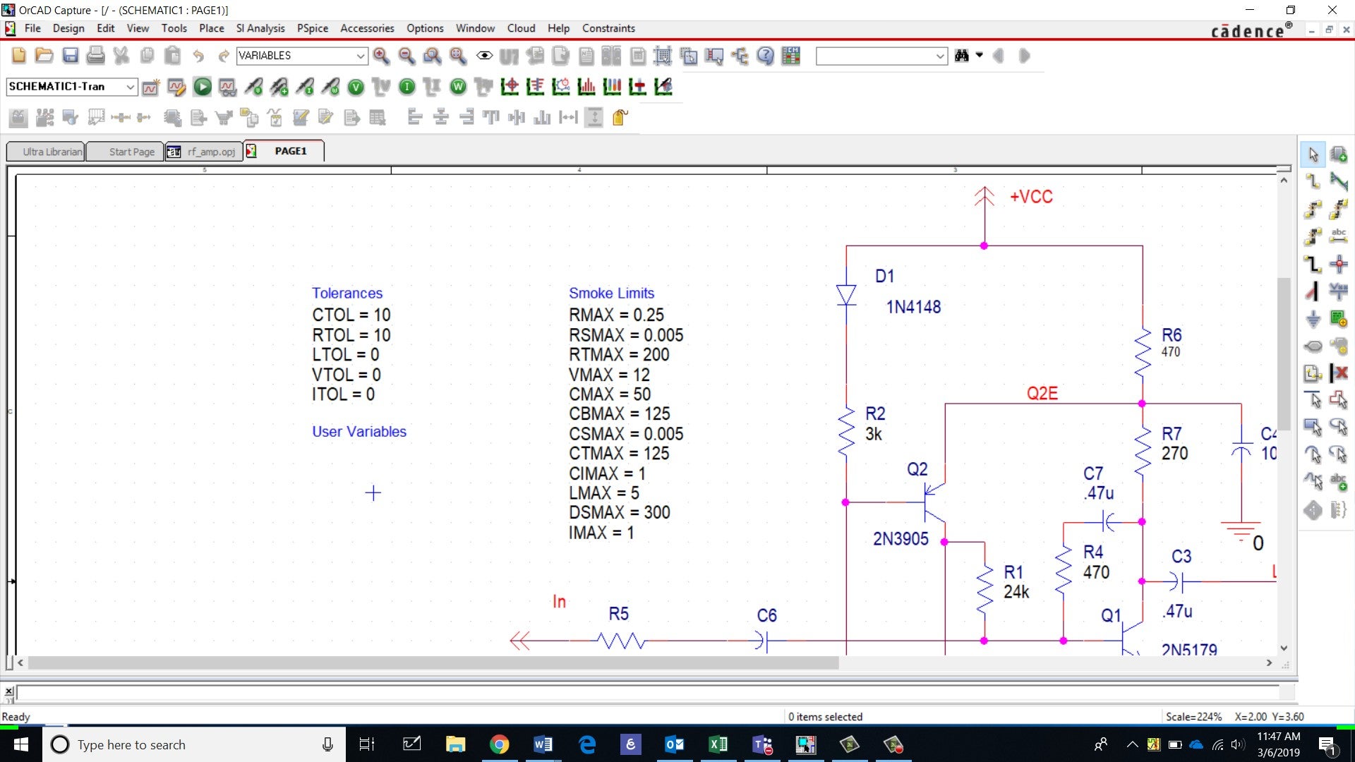
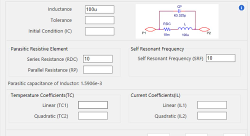
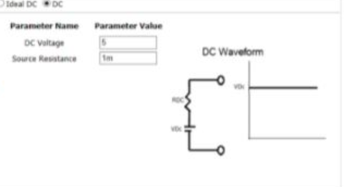
Step 2: Back in the schematic, ensure the following limits are set and run the transient simulation. Each component you would like included in the Smoke Analysis needs to have a limitation defined so it can be tested against measurements.
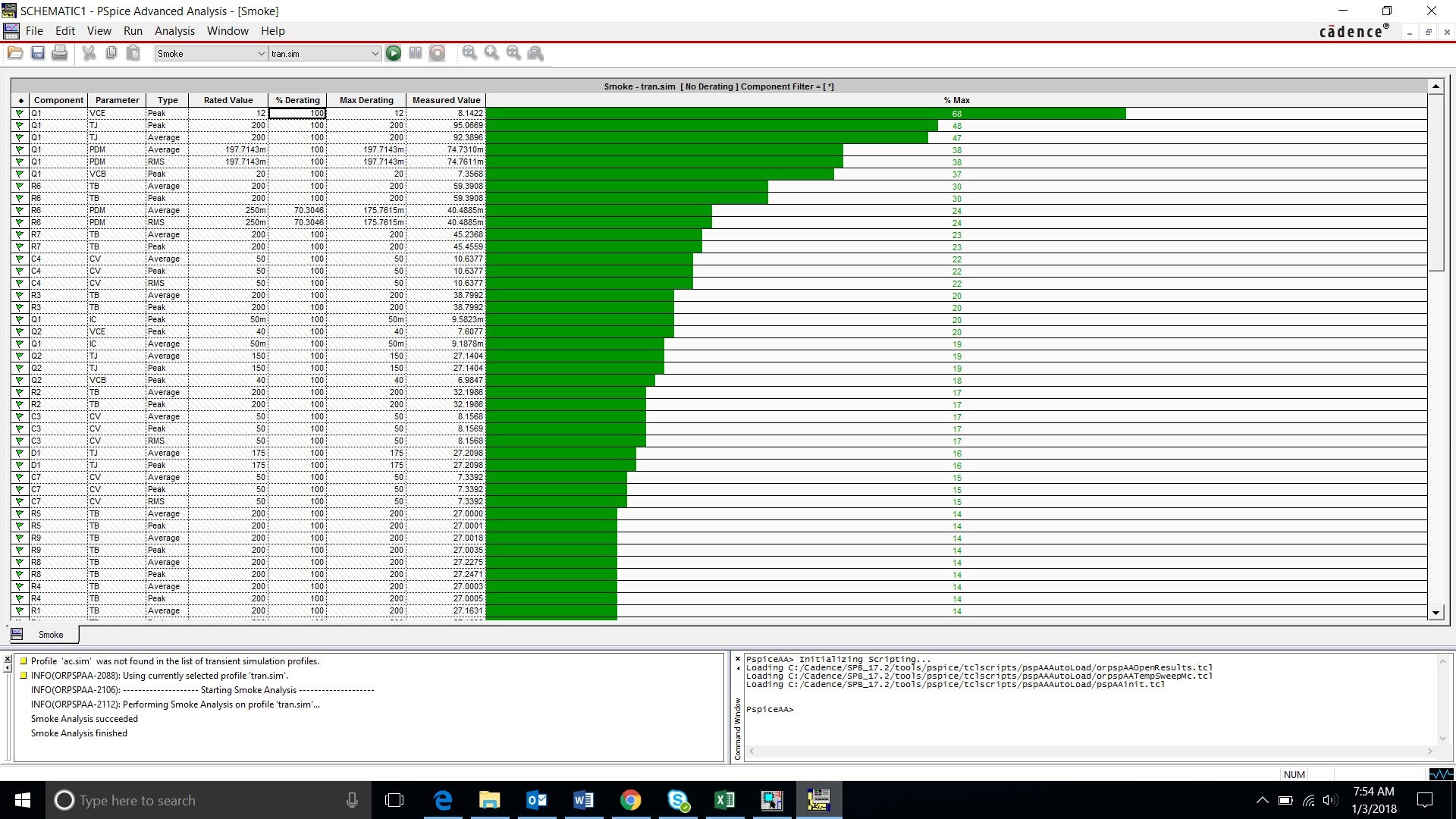
Step 3: Run the Smoke Analysis by selecting PSpiceà Advanced Analysis à Smoke from the toolbar and view the simulation.
We are only interested in the “Peak” measurements for this analysis. To hide values for Average and RMS measurements that are grayed out, right click and select “Hide Invalid Values”.
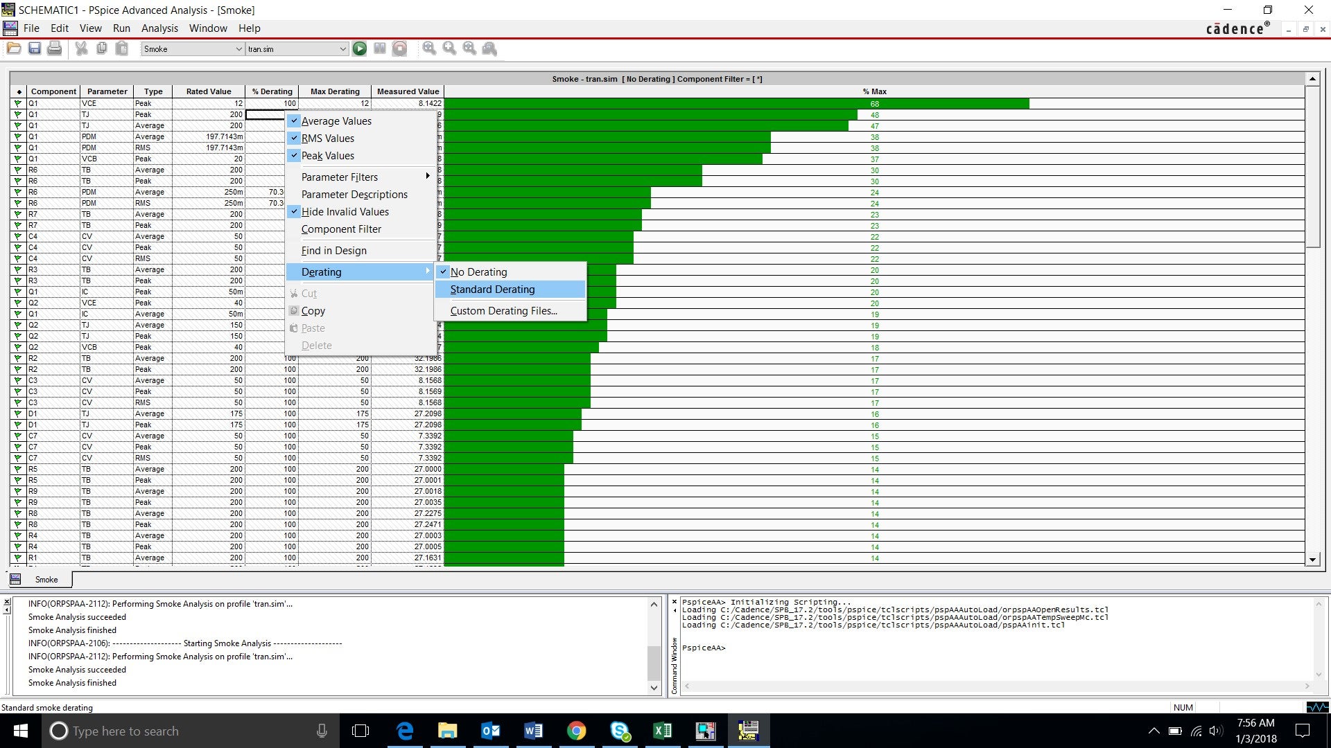
Step 4: Right click and select Standard Derating.
It is good practice to design with a standard margin of error to stay off the maximum limitations of a part. Standard derating percentages are used in the tool; however, percentages can be customized.
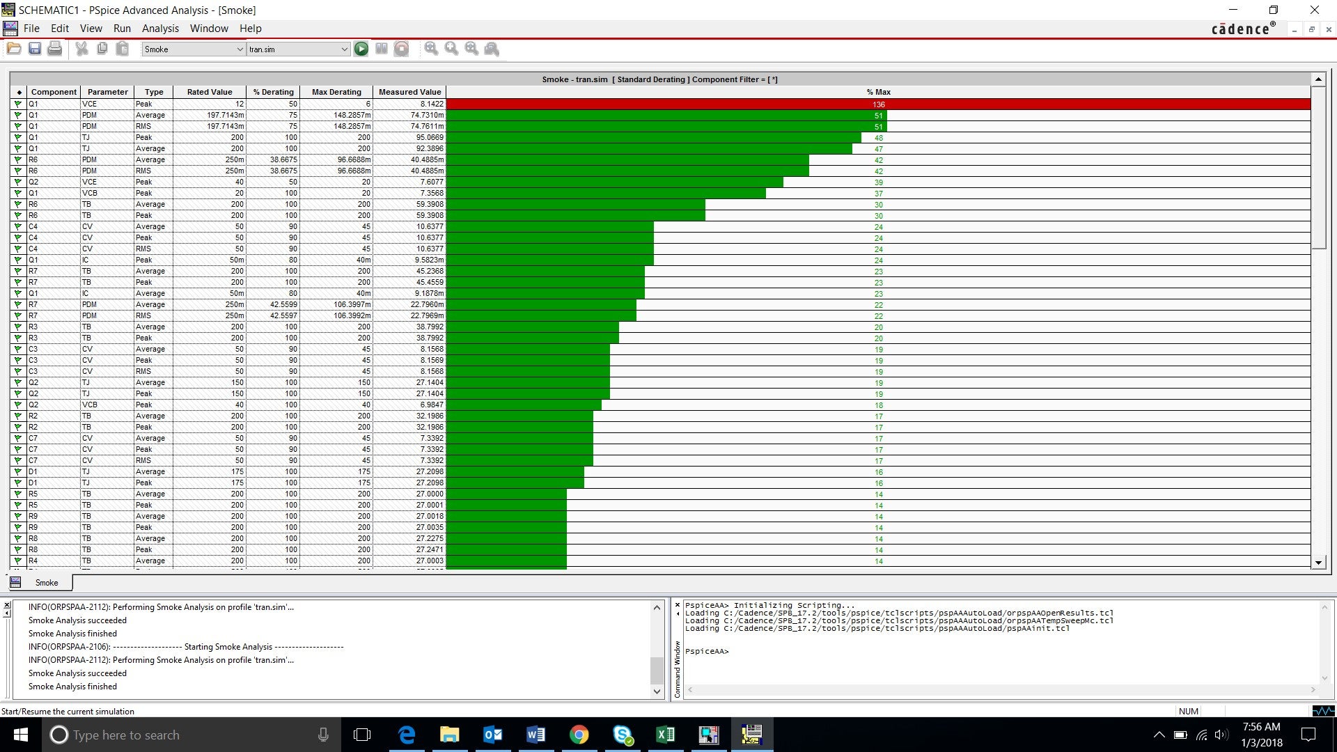
Step 5: Run the simulation again by selecting Run à Start on the toolbar.
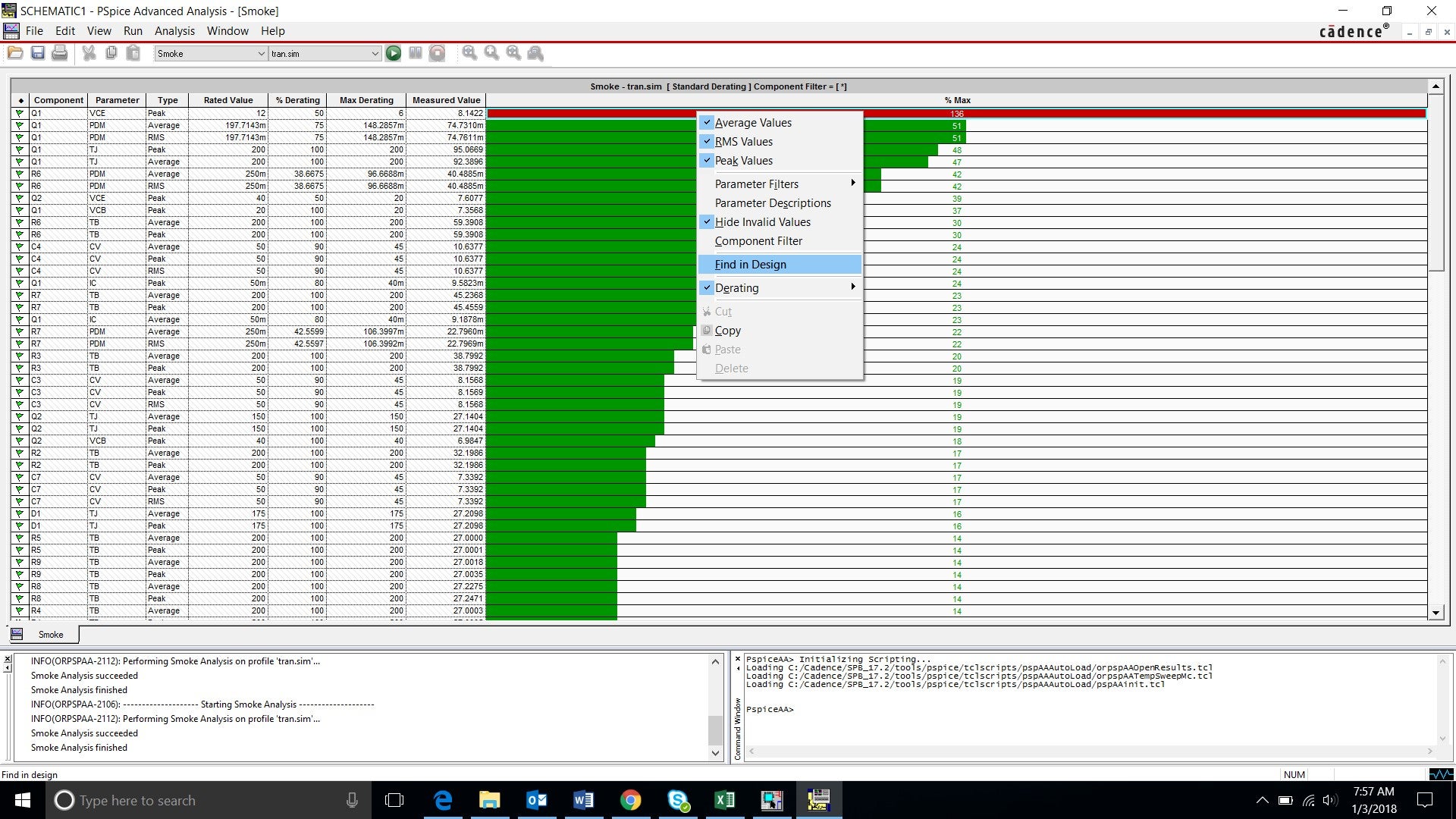
Step 6: Right click on the first line of the simulation (Component: Q1, Parameter: VCE) and select Find in Design. This will bring you to the schematic and highlight the problem component.
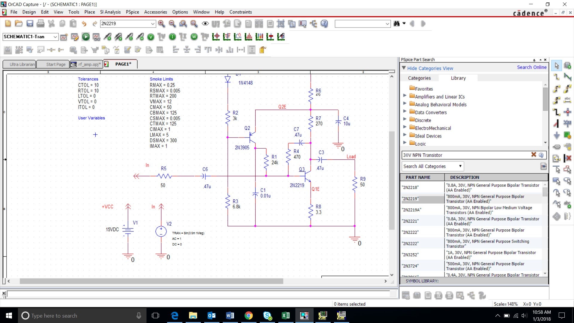
Step 7: Replace the problem component and delete Q1 from the schematic. From the toolbar Select Placeà PSpice Componentà Search. Search for “30V NPN Transistor”. Double click on the component “2N2219” and place the component where Q1 was located. Press (ESC) to end part placement.
Note: If the component is placed as “Q?”, double click the “Q?” and name the component Q3.

Step 8: Run the transient simulation followed by the Smoke analysis (PSpice > Advanced Analysis > Smoke)
Replacing the component has resolved the issue in the design.
Smoke Analysis in OrCAD PSpice Designer Plus will tell you what components in your design are going to have issues performing their duties and for what specific reason they will fail. If you make changes in your design and need to re-check your results, simply run the Smoke Analysis again. It allows you to proceed with confidence knowing that the components in your design are going to be able to stand up to whatever harshness they encounter, with a bit of room to spare.