Printed circuit board (PCB) design teams today have more software options than ever before. Two of the most widely discussed platforms are OrCAD vs KiCad. While both tools enable engineers to create schematics, design PCBs, and generate manufacturing outputs, they differ significantly in their capabilities, workflows, support models, and intended user base.
The right choice depends on factors such as project complexity, team size, compliance requirements, budget, and long-term design goals. This article examines the strengths and limitations of both platforms to help engineering teams make an informed decision.
Overview: OrCAD vs KiCAD
OrCAD X is a unified PCB design platform from Cadence Design Systems with applications for schematic, simulation, and PCB layout. It targets professional engineers and companies who need to create verified, accurate, production-ready designs. To support this, OrCAD X includes advanced features that support a collaborative team environment, such as constraint-driven routing, enterprise data management, and simulation baked into a single environment.
KiCad is a free, open-source EDA platform maintained by the KiCad Project and supported by a global community of contributors. It provides schematic capture, PCB layout, 3D visualization, and manufacturing output generation at no licensing cost. KiCad has experienced significant growth in recent years and is now used by hobbyists, startups, individual contractors, and some commercial product development teams.
Here are the scenarios where each of these tools works best:
- KiCad fits: Hobbyists, open-source developers, and individual contractors or freelancers who need fast, unencumbered workflows without subscription overhead, and do not need or want technical support.
- OrCAD X fits: Engineering teams that need technical support, correct by construction, integrated workflows, and the ability to scale.
OrCAD vs KiCad: PCB Layout and Routing
Both platforms support schematic capture, multi-sheet designs, PCB layout, Design rule checking, manufacturing output generation, and 3D board visualization. The differences become more apparent as design complexity increases.
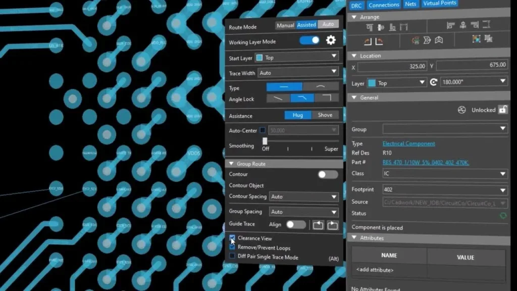
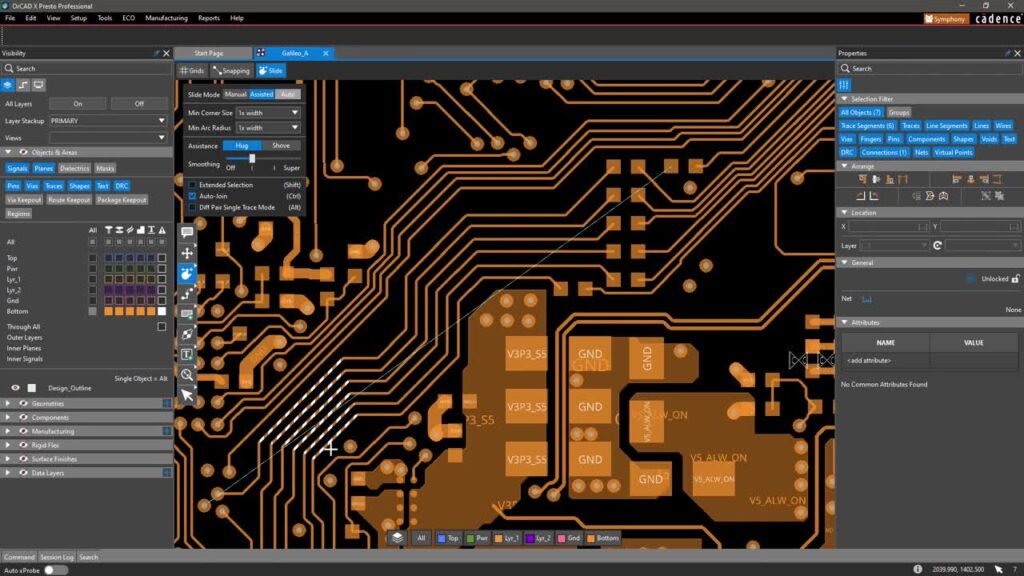
OrCAD X includes advanced constraint management and high-speed design support to manage increased design complexity. OrCAD X Constraint Management ensures designs meet performance, reliability, and manufacturability demands through a unified interface across schematic and layout environments, with dynamic feedback, hierarchical rule systems, and constraint grouping. You define timing delays, differential pair constraints, and impedance targets before placing a single trace. Additionally, OrCAD X includes advanced layout features such as placement replication, auto-interactive routing, AI integration, and more to help accelerate the PCB design. OrCAD X includes a full 3D canvas that supports real-time clearance checks and bidirectional ECAD/MCAD synchronization with SOLIDWORKS.
KiCad’s interactive push-and-shove router supports up to 32 copper layers, with differential-pair routing and trace-length tuning. Multi-channel design support in KiCad 9 lets you repeat PCB layout elements from one channel to create identical copies, a workflow that previously required manual duplication or expensive commercial tools. For 3D Visualization, KiCad’s 3D viewer is fast and interactive.
OrCAD vs KiCad: Design for Manufacturability and ECAD/MCAD Integration
Beyond routing, OrCAD vs KiCad diverges in two areas that directly affect downstream success: design for manufacturability (DFM) and ECAD/MCAD integration.
OrCAD X includes real-time DFM checks through DesignTrue DFM, with automatic rule configuration based on manufacturer specifications for fabrication, assembly, and testing. It also supports bidirectional SOLIDWORKS synchronization, keeping mechanical and electrical teams aligned without manual file transfers. KiCad offers post-layout DRC and STEP export for basic mechanical reference, but neither capability matches the depth of native OrCAD X integration.
| Capability | KiCad | OrCAD X |
| DFM Checking | Post-layout DRC with manually configured rules | Real-time DesignTrue DFM with automatic manufacturer rule configuration |
| Fabrication & Assembly Checks | Basic clearance and rule violations | Continuous checks for fabrication, assembly, and testability during layout |
| ECAD/MCAD Integration | STEP file export/import for 3D reference | Bidirectional SOLIDWORKS synchronization with live board model updates |
OrCAD vs KiCad: Simulation
Organizations pursuing a shift-left design methodology often place significant value on integrated simulation and verification, as these capabilities can significantly impact design quality and development timelines. When comparing OrCAD X and KiCad, simulation is a distinct area of difference:
- SPICE Simulation

KiCad includes ngspice integration for basic SPICE simulation.
OrCAD X includes native PSpice integration, enabling designers to run analog, mixed-signal, worst-case, and Monte Carlo analyses directly from schematic capture. This allows you to not only verify design functionality before prototyping but also optimize components and circuit performance to ensure design reliability, longevity, and more.
- SI/PI Simulation
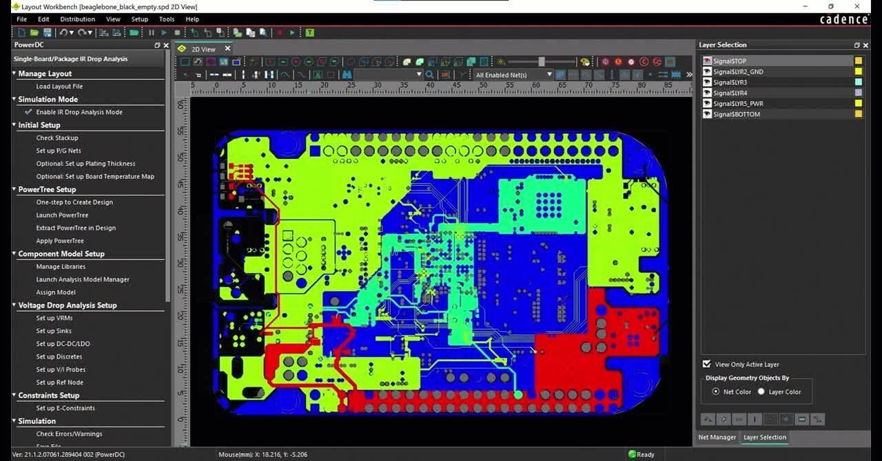
OrCAD X offers in-design SI/PI checks through the embedded Sigrity X Aurora engine, allowing trace impedance, coupling, return-path, and IR drop issues to be visualized directly on the PCB canvas, not as a post-layout batch job. This enables designers to identify SI and PI issues early in the design process and to make modifications during PCB layout, when changes are easiest.
For KiCad, post-layout SI/PI requires third-party tools; there is no native equivalent to Sigrity X Aurora.
OrCAD vs KiCad: Library Management and Team Collaboration
KiCad provides library creation and management capabilities, and in 2024, the KiCad library team added nearly 1,500 new symbols, 750 new footprints, and 132 new 3D models. However, organizations are responsible for establishing their own governance processes, approval workflows, and data management practices. Because KiCad uses plain-text file formats, teams can integrate projects directly with Git for version control. Distributed teams can manage schematic files and footprints with standard dev tooling such as Git, GitHub, or GitLab.
OrCAD X approaches data management differently. Centralized component databases ensure engineers pull only procurement-approved parts. Ultra Librarian, now part of Cadence, gives OrCAD X designers direct access to millions of verified symbols, footprints, and 3D models from more than 2,500 manufacturers, with every model built to IPC and ANSI standards.
Key OrCAD X collaboration features include:
- Workspaces (Cloud or on-premise): A centralized, secure platform for real-time team collaboration on library creation, design reviews, and version control, eliminating the version-conflict headaches common in file-based workflows, with options for both cloud and on-premise.
- Symphony Concurrent Design: Two-person real-time concurrent design on the cloud, with no stop-and-go or file transfers required.
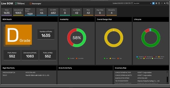
- Real-Time Supply Chain Analysis: OrCAD X provides real-time market intelligence on over 1.6 billion parts from 3,600 suppliers, helping engineers address component availability, lifecycle risks, and compliance with REACH and RoHS directly in the schematic design environment.
- Lifecycle Control: Tight integration with enterprise product data management (PDM) systems to track component obsolescence and compliance throughout the product lifecycle.
OrCAD vs KiCad: Pricing, Licensing, and Platform Support
Platform Support
KiCad runs natively on Windows, macOS, and Linux. KiCad’s support model is community-driven. Users can access documentation, forums, tutorials, and community resources.
OrCAD X is primarily Windows-based. OrCAD users typically have access to commercial support, training resources, technical assistance, and established service channels.
Pricing and Licensing
KiCad is completely free and open-source, with no net limits, no board size caps, and no seat restrictions. The only real cost is time, specifically, the time you spend building out library management processes or performing layout tasks manually that OrCAD X handles natively.
OrCAD X offers a flexible, scalable licensing model to fit your needs. This includes yearly leasing and perpetual licenses with technical support and product updates for both. The Cadence PCB design platform is fully scalable, allowing engineers to increase functionality and capabilities as their designs become more complex without requiring file translations.
OrCAD vs. KiCad: Final Recommendations
| Feature | KiCad 9/10 | OrCAD X |
| Pricing | Free / Open Source | Flexible licensing models to fit both your requirements and budget. |
| Operating Systems | Windows, Linux, macOS | Windows |
| Max Copper Layers | 32 | Unlimited |
| Schematic Simulation | ngspice (basic SPICE) | PSpice (analog, mixed-signal, Monte Carlo) |
| SI/PI Analysis | Third-party tools required | Sigrity X Aurora, in-design on PCB canvas |
| Collaboration | Git / plain-text version control | Cloud or On-premise workspaces, Symphony concurrent design |
| Component Library | Community-driven (1,500+ new parts in 2024) | Integration with online sources for verified models, such as Ultra Librarian and Samacsys. |
| Target Users | Hobbyists, independent contractors, open-source | Professional engineering teams who need automation and DFx capabilities for first pass success |
Choose KiCad if you are running a lean team, building open-source hardware, or working on designs without hard pre-layout SI/PI requirements. KiCad may be a good fit if:
- Budget is a primary concern
- You are an individual engineer, student, or startup
- Projects are relatively straightforward
- Open-source software aligns with organizational goals
- Internal processes can manage libraries and design governance
Choose OrCAD X if the cost of a board respin, in time, non-recurring engineering (NRE), and schedule, exceeds the cost of a software license. The ability to analyze trace impedance, coupling, return-path, and IR drop directly on the PCB canvas, combined with built-in DFM and live manufacturing rule-checking, provides teams with immediate feedback that reduces downstream respins. For DDR5, PCIe Gen 5, or any high-speed interface where signal integrity sign-off is a hard requirement, direct integration with Sigrity X for SI/PI analysis will help verify performance before production. OrCAD X may be a good fit for it:
- Designs involve high-speed or complex circuitry
- Simulation and analysis are important requirements
- Multiple engineers collaborate on projects
- Regulatory compliance or quality control is critical
- Centralized library and data management are priorities
Both OrCAD and KiCad are capable PCB design platforms that continue to evolve, and the optimal choice depends on an organization’s technical requirements, budget, team structure, and development processes. Ultimately, evaluating the full design process, not just PCB layout features, can help determine which platform best supports long-term engineering success.
EMA Design Automation is a leading provider of the resources that engineers rely on to accelerate innovation. We provide solutions that include PCB design and analysis packages, custom integration software, engineering expertise, and a comprehensive academy of learning and training materials, which enable you to create more efficiently.
For more information on OrCAD vs KiCad and how we can help you or your team innovate faster, contact us.