OrCAD PCB Design

Solve Your Toughest PCB Design Challenges with OrCAD

You need a dependable PCB design tool that can scale with your growing business. See why PCB design teams across the world depend on OrCAD to create high quality, reliable products. 

Over 50,000 Engineers & Counting

Instant Design Feedback While You Work

Your CAD tool should provide you with feedback when you need it, as you design, so you can make intelligent design decisions up front.  Get out of the Design – Check – Fix – Repeat cycle with the real-time design features only available in Cadence. With real-time design feedback, identify issues as they happen so you can address them when they are easiest to solve.

See Real-Time Design in Action >

Architected to Scale With You

The pace of change in electronics can be intense. You need a solution designed to keep up and grow with your needs. Stay ahead of the competition, technology changes, and innovate faster with the industry’s only fully-scalable design platform.

Explore OrCAD Design Suites >

Get Your Design Right the First Time

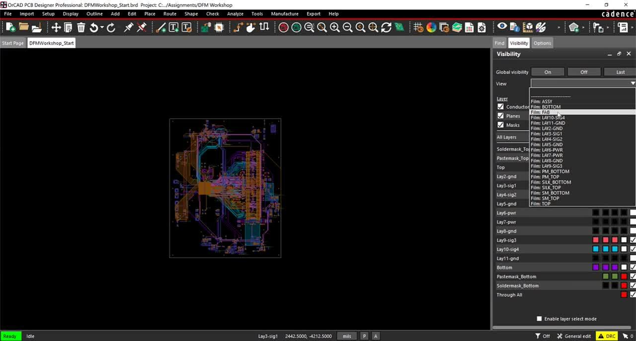
Getting boards back from manufacturing can be a nerve-racking experience, but it does not have to be. With the advanced DFM rule checking, real-time feedback, and analysis capabilities in OrCAD you can be confident your design will be up and running the first time.

Complete PCB Design Innovation Platform

OrCAD is built to support you from concept to production and beyond. With OrCAD, address all your design challenges in a single, unified environment.  Seamlessly get your design done on-time, the first-time by leveraging tools built to help you design for peak productivity, accuracy, and speed. Experience the future of PCB design with OrCAD.

CREATE

Industry Standard Schematic Capture

Design entry is powered by the world’s most used schematic capture solution, OrCAD Capture. Used on countless designs across all industries and levels of complexity, OrCAD Capture provides the perfect mix of ease of use and functionality to support your design requirements.

KEY CAPABILITIES

Easy & Intuitive

Quickly create clear and concise multi-page, hierarchical schematics with ease. Compare versions, generate bill of materials (BOM), and create pdf documentation at the touch of a button.

Integrated

Always know what changed with seamless sync of data between logical and physical. Integrated simulation engines let you perform analysis inside your schematic design environment, preventing rework and data loss.

Correct By Construction

Say goodbye to late-stage design changes with instant design feedback. Easily define and validate your design intent with real-time design rules checks, constraint definition, and pre-layout SI analysis. Then, seamlessly pass this data along to implementation—setting you up for design success right from the start.

Libraries Included

Be productive immediately with access to millions of popular CAD symbols footprints, and 3D models directly within the software. Libraries are the last thing you want to worry about and with OrCAD, you no longer have to.
DESIGN

Route with Precision and Accuracy

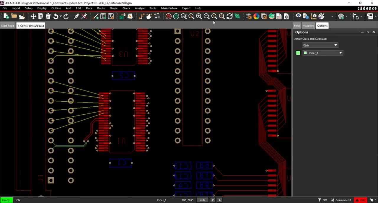
Over half of design cycle time can be spent in placement and routing. Complete even your most complex design with accuracy and speed with the industry’s leading PCB implementation solution and see how PCB design is meant to be.

KEY CAPABILITIES

Powerful Route Engine

Built on the Allegro PCB Editor architecture equals an unmatched placement and routing experience. 64-bit performance, real-time updates and feedback, intuitive interactive and automated routing, as well as comprehensive rules and route guidance support give you the tools needed to complete your designs fast and with confidence.

Instant Design Feedback

Don’t wait until the end of the project to find all the issues you need to fix and change. Get instant feedback as you design with on-canvas guidance and notifications, so you can solve issues before they have a chance to become an ECO.

Integrated 3D Engine

View, manipulate, and evaluate your design in 3D right from within the PCB design platform. Identify collisions, see how your design performs during flex bends, and view the effects of mechanical elements such as heat sinks and enclosures in realistic 3D. Quickly adjust and see changes update instantly.

Scalable & Extensible

As your needs grow, so can your design tool. Our unique, scalable architecture allows you to seamlessly add capabilities like advanced routing and team design as needed, all leveraging the same data model eliminating any needs for translation.
ANALYZE

Comprehensive Simulation and Analysis

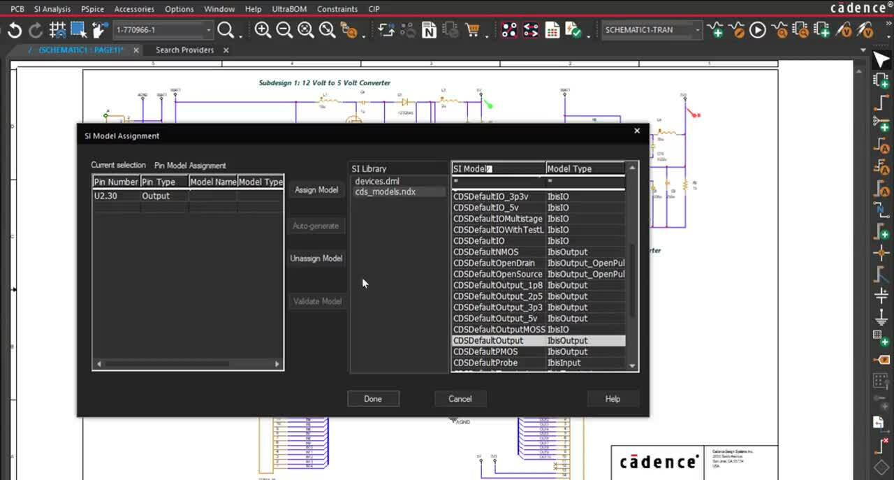
Know your design is ready for production with our complete set of analysis and simulation options. Run thousands of design scenarios, identify, and fix issues before the first physical prototype is ever produced.

KEY CAPABILITIES

In-design Analysis

Analyze your data where it is. Cadence analysis is deeply connected to the PCB design platform to provide quick and accurate analysis so you can easily take action. No clunky translation or time spent pushing data between tools.

Actionable Insights

Easily visualize and identify the impact of your analysis results. From improving yield and identifying parts likely to fail to displaying results of multi-gigabit simulations, you will have the guidance you need to make the right decision based on your simulations.

Optimize and Verify

Analyze your design at all stages of the process. Identify optimizations and test design alternatives early where the cost of change is lowest. Then take advantage of our unmatched accuracy and capacity to perform final sign-off and verification, all in one platform.

SI, PI, Thermal, and SPICE

Leverage a full suite of analysis engines and explore all aspects of your design from analog mixed-signal, signal integrity, power integrity, and even thermal affects. Mix and match engines easily to meet your design requirements and move to production with confidence.
BUILD

Go to Manufacture with Confidence

Sending your design to production can be a tense experience. Many have come to expect manufacturing changes and issues to happen, slowing the design cycle and often leading to long nights and weekends for the engineering team. It doesn’t have to be that way. Go to manufacturing with confidence knowing you have been checking for manufacturing issues along the way with our real-time DFM checking and rules support.

KEY CAPABILITIES

Instant DFx Feedback

If you can’t build it, you can’t release it. Leverage real-time DFx (manufacturing, test, fabrication, and assembly) checks as you design and get instant feedback if a potential manufacturing issue will occur.

Automated Manufacturing Outputs

Generating the correct files and providing accurate and clear documentation is critical for design success. With OrCAD, ensure a smooth manufacturing process without manual effort by automatically generating your design documentation and manufacturing output files.

Effortless MCAD Integration

Ensure fit and function by seamlessly synchronizing your design with mechanical before you build. Easily communicate and track changes between ECAD and MCAD so everyone is on the same page and your project is on track for success.

DesignTrue DFM

Collaboration with your manufacturing partner early and often is key to success. Bring this collaboration into your design with the DesignTrue DFM partner program. Easily bring your manufacturing partners’ design rules into your design and build a true, correct-by-construction flow by checking your design against your intended manufacturing line as you go.
MANAGE

Your Data Where You Need it, When You Need It

Keeping track of design revisions, managing part availability and compliance, and updating your PLM can seem like another job. OrCAD provides automated capabilities to handle these necessary tasks quickly and efficiently without having to leave your CAD environment. 

KEY CAPABILITIES

Automated Revision Control

Get rid of the needless email chains and finger pointing to try and figure out who changed what when. Easily manage design revisions with automated check-in, check out, easy roll-back, and complete design version history at your fingertips.

Seamless Team Design

When working in a team, ensuring everyone is on the same page is critical. Effectively collaborate with quick and easy definition of project responsibilities and access, and seamless communication among multiple team members.

Component Sourcing and Library Management

Reduce errors and remove redundancy through the deploy of a shared library that can be accessed by your engineering team. Augment component library data with part pricing, availability and lead times, and automatically update your projects as data changes. Make your part library a competitive advantage not a design challenge.

Enterprise Integration

Your design is often part of a whole and as such, will need to be managed in a company PLM system or similar. Easily synchronize your design data with PLM and surface contextual data from PLM such as corporate-approved part numbers directly in your CAD tool and ensure a smooth transition to production.
Learn More

Products

Explore the full breadth of OrCAD technologies. Designed to scale with your needs, you can easily select the technologies required to solve your unique design challenges while maintaining a common, flexible design environment that can grow as you do.

OrCAD PCB Designer Suite

Powerful, comprehensive PCB design packages

Complete PCB Design Solutions Including:

Schematic | Layout | Routing | Manufacturing | Analysis

Starting at $1,300 / year

OrCAD PSpice Designer Suite

Advanced virtual prototyping solutions for first pass PCB success

Complete Analog / Mixed Signal Analysis Including:

Schematic | SPICE simulation | Reliability Analysis | Electro-Mechanical Sim 

Starting at $2,400 / year

Compare PCB Design Suites

Schematic Entry and Libraries
OrCAD Capture Schematic Entry
Hierarchical and Multi-Sheet Schematics
Snap Functions and Grids
Block Diagram Support
Schematic Symbol Editor
Starter Library with Integrated Cloud Library of Millions of Symbols, Footprints and 3D Models and Custom Library Creation
Comprehensive Project Hierarchy
Rule Definition and Management with Real-Time Design Rule Checking
Open Design Framework
Integrated Spice and SI Simulation
Automated Design Cache
Customizable Component Properties and Bill of Material (BOM) Creation
Graphical Design Compare
Automated Annotation/Back Annotation and Ref Des Assignment
Intelligent PDF Output of Schematic
Built-in Translators (Altium, Mentor, Eagle, more)
PCB Layout Creation and Automatic Netlist Generation within your Schematic
Component Data Management
Integrated Access and Component Placement from a Centralized Component Database
Integrated Part Manager
Part Status Notification
Design Variant Support and Color-Coded Variant Display
Parametric Part Search
Temporary Part Management
Symbol and Footprint Preview
Automated Zero-Touch Bill of Material (BOM) Creation
BOM Templates
Relational BOM Support
BOM Variant Support and Variant Reporting
Cloud Enabled Services
Cloud-Based Workspaces
Customizable Permissions
File Management and Version Control
Integrated Part Authoring and Management
Promoted Library of Symbols and Footprints
Automatic Population of Parametric Information
Association of Simulation Models, Symbols, Footprints, and Datasheets
Managed User Roles
LiveBOM: Real-Time Supply Chain Analysis
Advanced PCB Layout and Routing
Real-Time Design Synchronization
Cross Probing and Cross Placement of Components Between Schematic and PCB
Automated Intelligent Component Placement Using Quick Place
Component Footprint and Padstack Wizard and Editor
SKILL (programming language, runtime, macro and scripting support)
Cross Section Support and Editor with Unlimited Layers
Splitplane Support
Dynamic Shapes and Pad Suppression with Real-Time Plowing and Healing
Extended Net (XNET) Creation and Rules
Differential Pair Support
Automatically Route Nets by Pick
Interactive and Advanced Routing
Stacked Via Edit and Move
Blind and Buried Via Support
Intelligent PDF Output from Board Design
Import/Export of Cross Section, Colors, Design Rules and Parameters
Design Review and Markup
Autorouting
Interactive Delay Tuning
Dynamic Heads-up Display for Critical Nets
Group Route Via Pattern and Via Array/Shielding
Segment Over Void Detection
Placement Replication
Symphony: PCB Co-Design
Rule-Based Design
Constraint Manager
Physical and Spacing Rules
Via-in-Pad and Pad Entry/Exit rules
Differential Pair Rules
DFx Rules and Checks
Real-time Active Design Rule Checks (DRC)
Constraint Manager Analysis Mode
Electrical Rules
Layer Set and Matched Group Rules
Propagation Delay Rules
Pin Delay Inclusion and Z-Axis Delay Support
Region-Based Rules
Return Path Rules
3D Clearance Rules
Automated Rigid Flex Design
Region-Based Rules
Inter-Layer Checks
Hug Contour Routing
Multi-Cross Section and Zone Table Chart Support
Dynamic Zones with Cross Hatch and Solid Planes
3D ECAD/MCAD Co-Design
3D Visualization with Collision Detection
Interactive 2D/3D Cross Probing and Cross Placement
3D Bending (FLEX)
MCAD/ECAD Incremental Design Data Exchange (EDMD)
Mechanical CAD Interface
Bi-Directional OrCAD and SOLIDWORKS integration (MCADX)
3D Clearance Checking and Design Rule Violations
In-Design Simulation and Analysis
Transient, DC, AC, Bias Point PSpice Analysis
PSpice Modeling Applications
Digital and Basic Analog Device Libraries
Waveform Analysis
IBIS Model Support
Pre-Layout Signal Integrity Analysis
Post-Layout Signal Integrity Analysis
Real-Time Impedance and Coupling Analysis
Placement Density Analysis
Real-Time Electrically Aware Placement Vision to Optimize PCB Layout
Real-Time Visual Routing Trace Optimization and Identification of Common Traces Issues
Manufacturing, Assembly, and Testing Support
Output Formats: Gerber 274x, NC Drill, NC Route, IPC-2581, ODB++, IPC-D-356 Netlist
PCB DesignTrue DFM Wizard and DFM Partner Portal Access
Embed Assembly Notes and IPC-2581 Specs Within PCB
2D Drafting and Dimensioning
Automatic Silkscreen Generation
Variant Assembly Drawing
One-Click Release to Manufacturing Export
LiveDoc: Real-Time Manufacturing Documentation
PCB Panelization
Dynamic Shaped-Based Fillet Support and Line Fattening
Backdrilling
DFT: Automatic Test Prep, Test Point Rules
Capture_CIS

OrCAD Capture

One of the most powerful design environments for taking today’s product creation from concept to production. Quickly, easily, and intuitively create complex schematic designs with hierarchical, reuse, and variant design capabilities.

Buy | Free Trial | Learn More

Constraint Designer EE

Make your design requirements an inherent part of the design process. A unique, wizard-based approach quickly defines requirements for your critical nets (such as DDR) and drive this data into PCB implementation for accurate and fast PCB layout and routing.

Buy | Learn More

OrCAD Capture Cloud

Access OrCAD Capture wherever you are with OrCAD Capture cloud. View, design, and evaluate schematics all within your browser.

Free Access | Learn More

PCB Editor Pro

OrCAD PCB Editor

OrCAD PCB Editor provides a concept to production design environment. Achieve design success with powerful PCB Design capabilities, scalable design environments and proven technology.

Buy | Learn More

OrCAD Documentation Editor

Quickly create the necessary manufacturing drawings to drive PCB Fabrication and Assembly with OrCAD Documentation Editor. With intelligent automation, complex PCB documentation is created accurately in a fraction of the time, ensuring manufacturing success.

Learn More

OrCAD DFM Checker

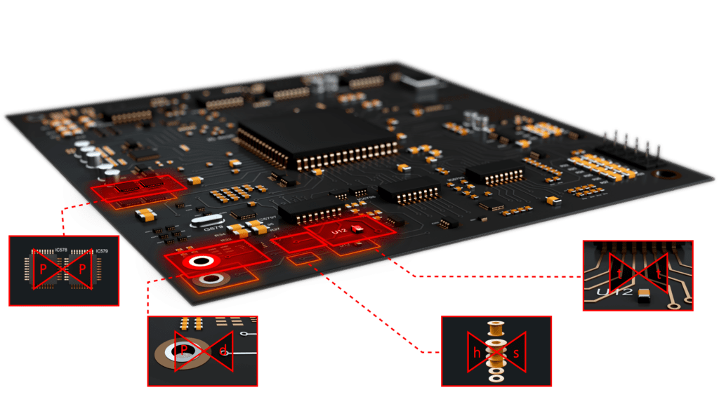
Easily identify issues in your design created during the manufacturing process with OrCAD DFM Checker. Perform a comprehensive manufacturing analysis while you design and address potential issues before fabrication to avoid time-to-market delays and costly re-designs.

Learn More

PCB Clustering for OrCAD

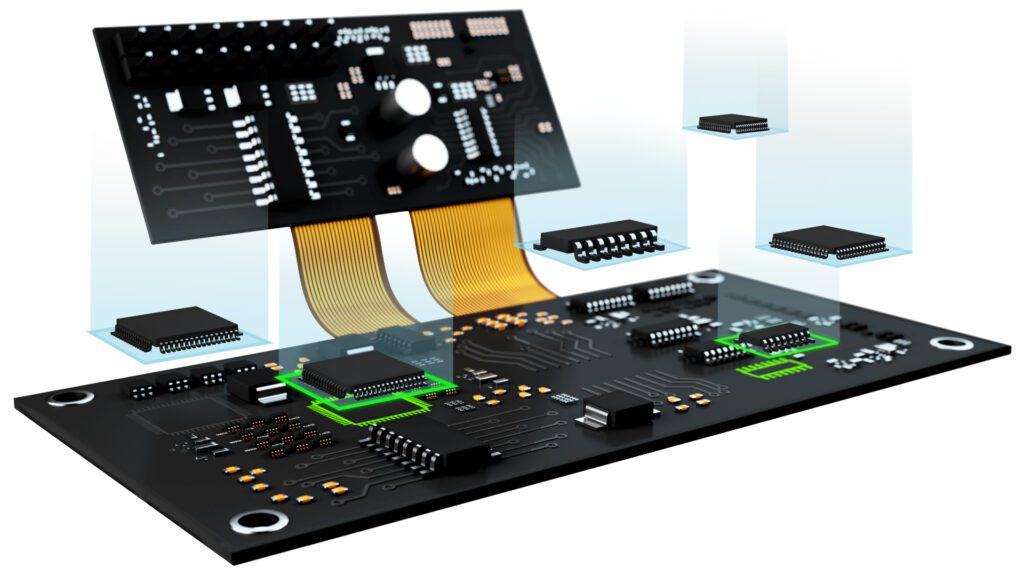
PCB Clustering for OrCAD provides AutoClustering technology, intelligent design (IP) reuse, and replication technology that can significantly reduce board placement time.

Buy | Learn More

Productivity Toolbox

OrCAD Productivity Toolbox provides a comprehensive suite of utilities designed to increase efficiency throughout the PCB design. With the enhancement and optimization of existing PCB layout capabilities, you can save time on monotonous tasks and focus on design.

Learn More

Pspice Advance analysis

PSpice

Optimize your designs and improve reliability, predictability, yield, and cost with an industry-leading, complete circuit simulation and verification solution.

Buy | Learn More

Sigrity Aurora

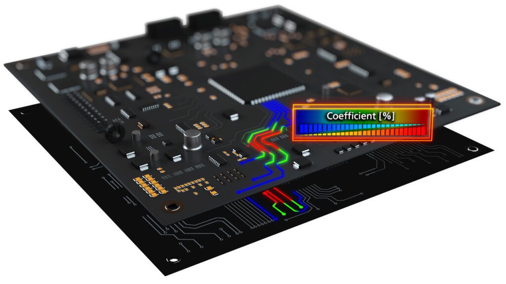
Detect and correct signal and power integrity issues throughout your PCB design with the integrated technology of Sigrity Aurora. Sigirty Aurora users can perform pre-layout analysis using “what-if” scenarios to develop accurate design constraints and confirm circuit functionality with in-design and post-layout analysis ultimately reducing design iterations.

Learn More

Sigrity

Easily screen a PCB design for signal quality without having to be a signal integrity expert. With Sigrity go beyond the simple geometry-based DRC and evaluate the entire design for impedance discontinuities, excessive crosstalk, return path discontinuities and more.

Learn More

AWR

Develop physically-realizable electronics ready for manufacturing and ensure success of your RF/Microwave designs with AWR. AWR allows you to model, simulate and verify all aspects of your design, including complex integrated circuits, packaging and PCB’s.

Learn More

EDM_4 (1)

OrCAD Engineering Data Management

Control your design data without ever leaving the OrCAD environment with revision control for schematic, PCB, and components. With OrCAD Engineering Data Management you can communicate, track changes, and ensure accurate and efficient team collaboration.

Learn More

OrCAD Component Information Portal

Part creation, verification and management is made easy with OrCAD CIP. Streamline your design process with a centralized part database to ensure the correct symbols and footprints are used by the entire team.

Learn More

SE CONNECT BOM Risk

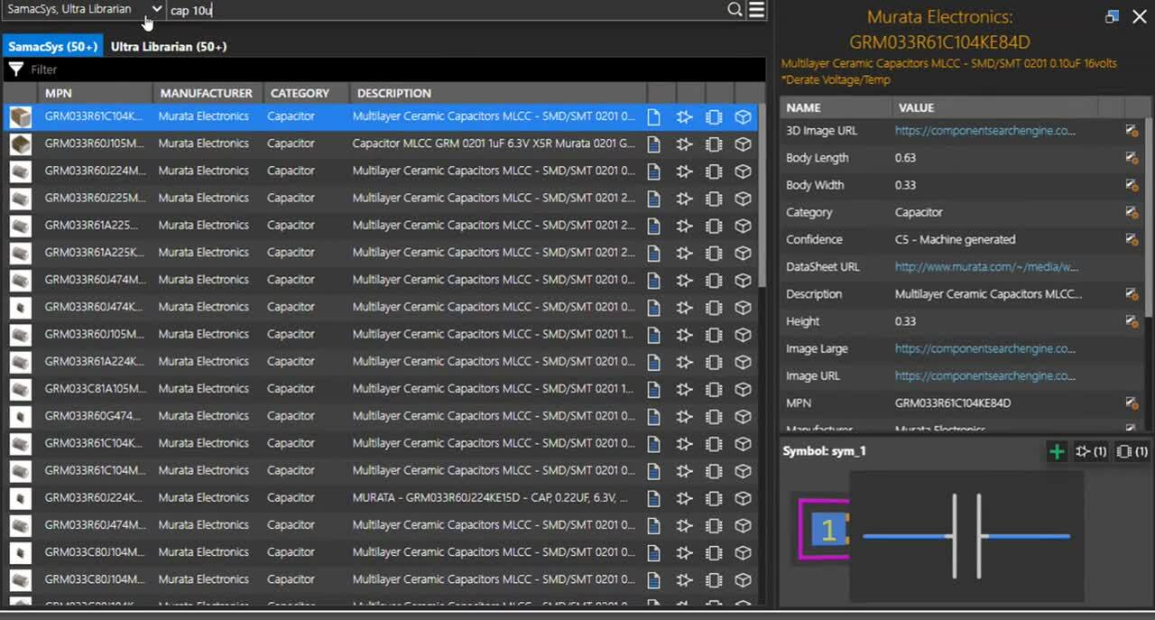
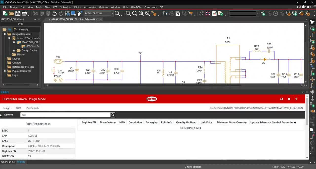
Optimize part selection and ensure design success by analyzing components for availability, compliance, and reliability during schematic creation within OrCAD.

Buy | Learn More

UltraBOM

Frustration-free part purchasing and BOM creation with live distributor information directly within OrCAD.

Free Download | Learn More

Enterprise Connect

Seamless integration between your PCB Design environment and your PLM, MRP or ERP systems ensures design success by incorporating product lifecycles and inventory into your design decisions.

Learn More

How to Buy

Buy OrCAD

Get started with the only PCB Solution built to grow with you. 

For Students

Students have access to a full OrCAD academic license. 

EMA Design Automation